Recording apparatus and liquid ejection head
a technology of liquid ejection and recording apparatus, which is applied in the direction of printing and inking apparatus, etc., can solve the problems of increasing the discharge of ink for recovery, affecting the quality of ink recovery, and affecting the impact of ink droplets, so as to inhibit the increase of the viscosity of ink
- Summary
- Abstract
- Description
- Claims
- Application Information
AI Technical Summary
Benefits of technology
Problems solved by technology
Method used
Image
Examples
first embodiment
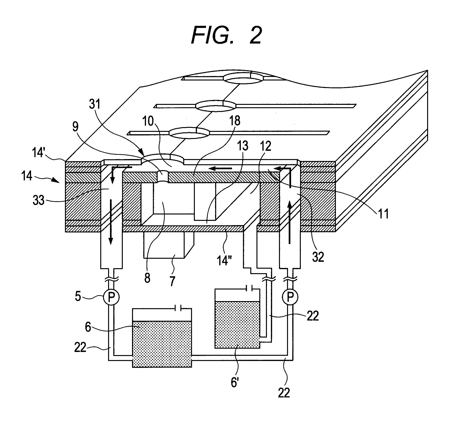
[0033]FIG. 2 is an enlarged sectional view of a recording head according to a first embodiment of the present invention. FIGS. 3A and 3B schematically illustrate, on an enlarged scale, a neighborhood of a first opening 9, in which FIG. 3A schematically illustrates, on an enlarged scale, the top of the neighborhood of the first opening 9, and FIG. 3B schematically illustrates a section taken along line 3B-3B in FIG. 3A.
[0034]The recording head is constructed by a substrate (not illustrated) on which a circuit and a piezoelectric element which will be described subsequently are provided, and a flow path forming portion 14 in which a first opening 9 and a flow path through which an ink flows are formed.
[0035]In the interior of the flow path forming portion 14, are provided an ejection orifice plate 18 in which a plurality of first openings 9 is provided passing through the plate, an individual liquid chamber 8 provided for each of the respective openings 9 and formed by using the eject...
second embodiment
[0046]FIGS. 4A and 4B schematically illustrate the construction of a recording head according to a second embodiment of the present invention, in which FIG. 4A schematically illustrate, on an enlarged scale, the top of the neighborhood of a first opening 9, and FIG. 4B schematically illustrates a section taken along line 4B-4B in FIG. 4A. Incidentally, the same portions in this embodiment as in the first embodiment are given the same characters, and the detailed descriptions thereof are omitted.
[0047]In this embodiment, the circulation flow path 11 is not exposed to the outside from the surface layer 14′ of the flow path forming portion 14 of the first embodiment. However, a second opening 31 having an opening area larger than that of the first opening 9 is provided at a position corresponding to the first opening 9 in the surface layer 14′. The opening corresponding to the circulation flow path 11 may not be formed in the surface layer 14′, or the opening corresponding to the circu...
third embodiment
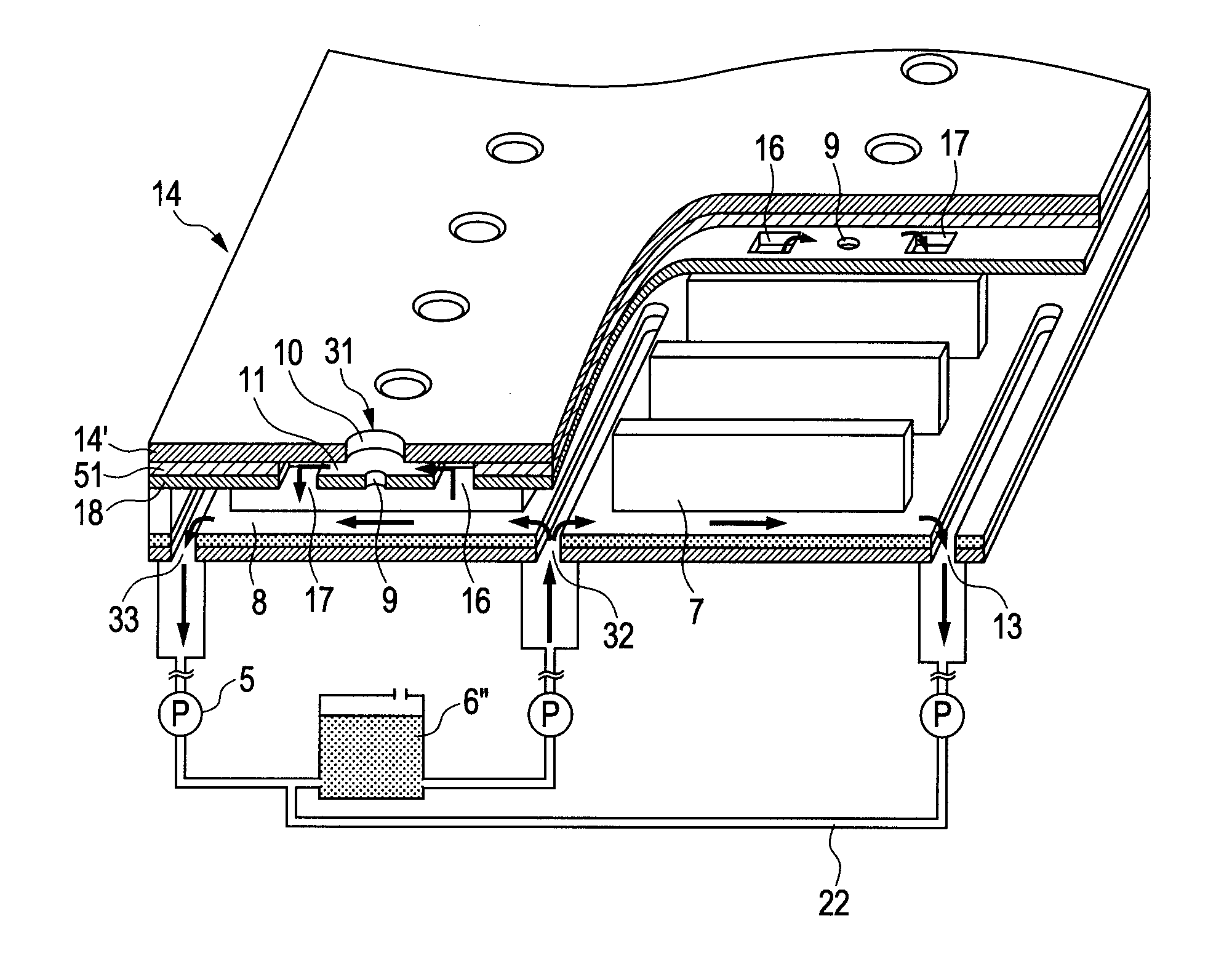
[0049]With respect to the same constructions as in the above-described embodiments, the descriptions thereof are omitted. In the embodiment illustrated in FIG. 5, a pump is also provided as a flow unit of the ink in the ink flow path 22 connecting the ink tank 6′ to the common liquid chamber 12 in the recording head of the first embodiment illustrated in FIG. 2. The ink is thereby caused to flow to the circulation flow path 11 through the first opening 9 and the ink reservoir 10 from the individual liquid chamber 8 even in a non-ejecting state as illustrated in FIG. 5. Therefore, the ink in the first opening 9 can be caused to flow without local retention. It can thereby be effectively inhibited to cause a concentration distribution by the retention of the ink in the first opening 9. In addition, the influence of the viscosity increase of the ink by the evaporation from the portions exposed to the outside in the ink reservoir 10 and the circulation flow path 11 can be more effective...
PUM
 Abstract
Description
Claims
Application Information
 - R&D
- Intellectual Property
- Life Sciences
- Materials
- Tech Scout
- Unparalleled Data Quality
- Higher Quality Content
- 60% Fewer Hallucinations
Browse by: Latest US Patents, China's latest patents, Technical Efficacy Thesaurus, Application Domain, Technology Topic, Popular Technical Reports.
© 2025 PatSnap. All rights reserved.Legal|Privacy policy|Modern Slavery Act Transparency Statement|Sitemap|About US| Contact US: help@patsnap.com


