
Torsional vibration damper

a technology of torsional vibration and damper, which is applied in the direction of hose connection, coupling, hoisting equipment, etc., can solve the problems of torsional vibration, damage to the grip means of the robot arm, and poor ride feeling of the timing gear or crankshaft, so as to achieve the effect of high quality and easy and simple assembling process

Active Publication Date: 2013-08-27
FUKOKU KOREA
View PDF8 Cites 23 Cited by
  • Summary
  • Abstract
  • Description
  • Claims
  • Application Information

AI Technical Summary

Benefits of technology

[0009]The present invention is made to solve the above problem about the torsional vibration damper, and the object of the invention is to provide a high quality lightweight torsional vibration damper to be mountable on the crankshaft firmly with easy and simple assembling process.

Problems solved by technology

In general, as a periodical torque acts on the crankshaft of the vehicle engine, a torsional vibration may be generated.
If the rotation speed of the crankshaft reaches to a certain point, then the torsional vibration may resonate with the proper vibration of the crankshaft itself to incur a serious vibration, which results in a bad ride feeling and damages of the timing gear or crankshaft.
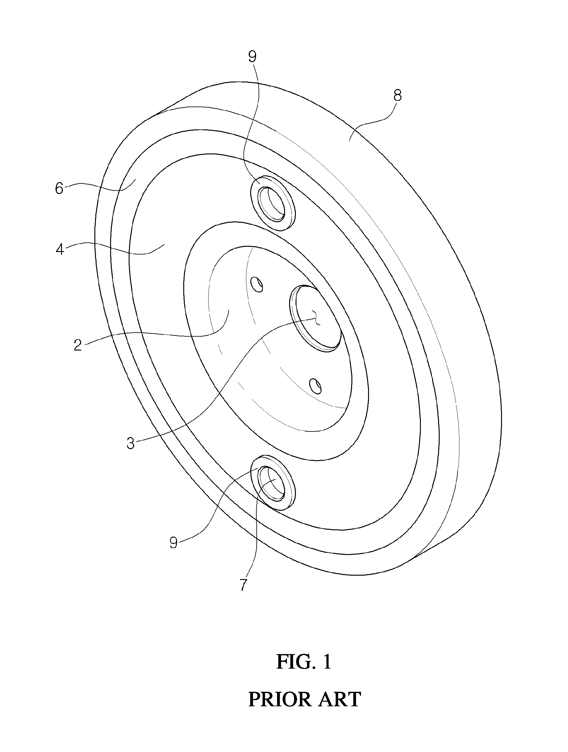
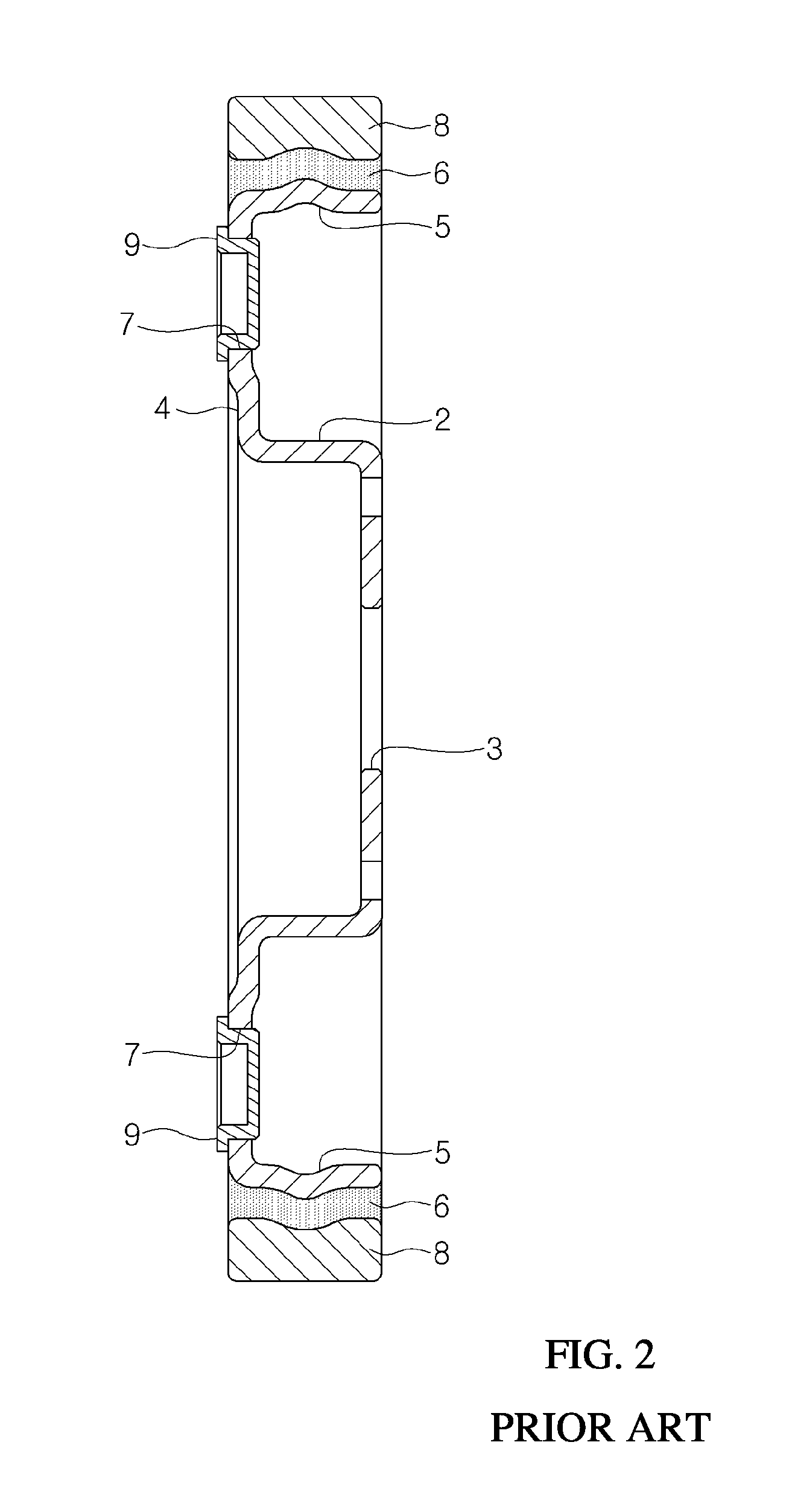
But the size of the grip hole 7 is relatively small, so the grip means on the robot arm could not be speedily and correctly aligned with the grip hole 7 of the disc 4, and it is not easy to control the robot arm to pick up the damper.
If the disc 4 is thin, the contact area between the grip means of the robot arm and the grip hole 7 may be also small, so the grip means could not firmly grip the damper, or the grip hole 7 may be deformed, so that the damper pulley could not be firmly assembled on the crankshaft, or assembling error may happens.
But the step of inserting the hole cap 9 into the grip hole 7 is rather cumbersome, and the hole cap 9 may drop out from the grip hole 7.

Method used


Image

  • Torsional vibration damper
  • Torsional vibration damper
  • Torsional vibration damper

Examples


Embodiment Construction

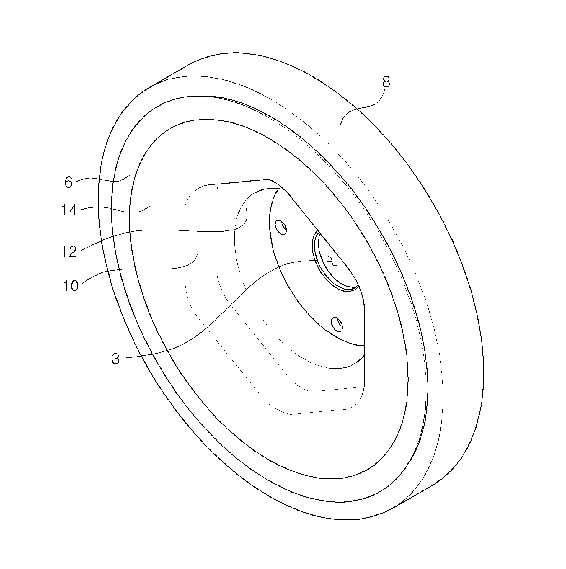
[0026]Referring to FIG. 3 to FIG. 5, the preferred embodiment of the invention is explained. As shown in FIGS. 3 to 5, the invention includes a hub 12 including a circular side wall 15 having a central hole 3 to be inserted on a crankshaft and a short cylindrical portion 16 being bent from the outer end of the circular side wall 15, a disc 14 which is integral with and extending from the hub 12, and a rim 5 being bent and extending from the periphery of the disc 14 in the parallel direction with the crankshaft.

[0027]A rubber layer 6 is attached on the outer surface of the rim 5 to absorb the vibration. And a ring member 8 is inserted on the outer surface of the rubber layer 6, which functions as a weight body of the damping mechanism. A pulley (not shown) having a plurality of groove on the outer surface is engaged on the outer surface of the ring member 8. Preferably, the ring member 8 and the pulley are formed with separate members, but the ring member 8 and the pulley may be made...


PUM


Abstract

A torsional vibration damper which comprises of a hub 12 having a central hole 3 to be inserted on the crankshaft and being formed to have a recess opened on one side, a disc 4 extending from the hub 2, a rim 5 being bent and extending from the periphery of the disc 4, a rubber layer 6 attached on the outer surface of the rim 5, and a ring member 8 or pulley inserted on the outer surface of the rubber layer 6, wherein a polygonal recess 10 is formed on the connecting area between the hub 2 and the disc 4 so that the polygonal recess 10 surrounds the hub 2.

Description

BACKGROUND OF THE INVENTION[0001]1. Field of the Invention[0002]The invention relates to a torsional vibration damper, and more particularly to a torsional vibration damper which could be easily assembled on the crankshaft with sufficient clamping force to achieve a high quality torsional vibration damper with easy assembling.[0003]2. Description of the Related Art[0004]In general, as a periodical torque acts on the crankshaft of the vehicle engine, a torsional vibration may be generated. The larger the rotating force of crankshaft is, the more the torsional vibration is, and the longer the length of the crankshaft is or the smaller the rigidity of the crankshaft is, the more the torsional vibration is. If the rotation speed of the crankshaft reaches to a certain point, then the torsional vibration may resonate with the proper vibration of the crankshaft itself to incur a serious vibration, which results in a bad ride feeling and damages of the timing gear or crankshaft.[0005]In ord...

Claims


Application Information

Patent Timeline
Patent Type & Authority Patents(United States)
IPC IPC(8): F16D3/76
CPCF16F15/126Y10T403/1608F16F15/10F16F15/22
Inventor SHIN, SEUNG-WOO
Owner FUKOKU KOREA
Learn More