Active hydrostatic bearing, particularly for internal combustion reciprocating engines, and a fluid handling system associated therewith

a technology of hydrostatic bearings and hydrostatic pressure, which is applied in the direction of bearings, liquid cushion bearings, shafts and bearings, etc., can solve the problems of reducing the power density of engines, reducing the efficiency of thermal and overall engines, and large mechanical energy consumption

Inactive Publication Date: 2013-09-03
OLEDZKI WIESLAW JULIAN
View PDF6 Cites 1 Cited by
  • Summary
  • Abstract
  • Description
  • Claims
  • Application Information

AI Technical Summary

Benefits of technology

[0016]Thus a principal object of the present invention is to provide a novel externally pressurized fluid bearing capable of bearing extremely high loads while retaining minimal internal friction.
[0017]Another principal object of the present invention is to provide an effective bearing system for supporting a shaft loaded with predetermined loads.
[0019]Yet more specifically, it is an object of the present invention to provide an effective bearing method for extremely high combustion pressure positive displacement internal combustion engines destined to work primarily at nominal (design) loads.

Problems solved by technology

Internal combustion reciprocating engines (Diesel and Otto cycle), most common prime movers in use, are responsible for substantial percentage of total hydrocarbon fuels expenditure and environment pollution.
The compression stroke of conventional Diesel engine is responsible for large mechanical energy consumption, which substantially diminishes engine's power density, and for diminished thermal and overall engine's efficiency.
However, HCCI and detonation cycles utilizing stoichiometric fuel / air mixture develop extremely high maximum pressures and gradients of pressure (understood as a function of angle of rotation of engine's shaft), which can destroy the engine.
Thus engine's strength, and particularly bearings capability to withstand extremely high specific loads and their ability to last for an economically reasonable period becomes a serious concern.
However, increased diameter of crankshaft journals causes points on the circumference of the journal travel at increased tangential velocity, which substantially increases bearing's loads.
Moreover, the mass forces are increased, which additionally increases bearings loads.
All these render the engine bearings prone to defects, and increased friction losses could nullify gains in thermal efficiency.
On the other hand, plain bearings in engine application have serious disadvantages and limitations.
Second, in this application, fluid bearings are subject to severe wear during start-up and shutdown, and substantial wear is also caused by hard combustion contaminants that bridge the oil film.
Third, friction losses and therefore power consumption are typically higher than rolling bearings due to microscopic roughness of bearing surfaces.
Fourth, fluid bearings can catastrophically seize under shock situations.
Fifth, the half frequency whirl met with in fluid bearings is the bearing instability that generates eccentric precession which can lead to poor performance or life.
In contrast, a conventional rolling bearing requires many high-precision rollers and the inner and outer races are often complex shapes, making them difficult to manufacture and rising the first cost of a machine.
Moreover, conventional rolling-element bearings usually have shorter life and require regular maintenance.
Moreover, rolling element bearings work much better under start-up and shutdown conditions, and generally work well in non-ideal conditions.
However Bonaccorso bearing is a passive bearing, i.e. a bearing that is unable to dynamically compensate for impending shaft motion leading to rubbing of rotating and stationary elements.
To be more precise, there is no active fluid handling system that can respond to rapidly changing loads of the shaft.
Moreover, this bearing lacks simplicity of plain bearings.
Unfortunately the method of Bently and Grant calls for excessively complicated equipment, and their fluid handling apparatus is likely to be slow in response to rapidly changing forces loading the shaft.
However, in this design the valves are directly controlled by shaft's radial movement, which is certainly to small to effectively command the valves.
However, Bently bearing is a passive one and its ability to bear extremely high shock loads is a suspect.
It is clear that complicated and expensive bearing system would be acceptable only in highly loaded expensive machines destined for sustained operation, wherein friction losses are responsible for substantial portion of overall operating costs, and large stationary and marine engines are definitely machines of this type.
As is well known, large stationary and marine engines are destined for operating primarily at nominal (design) loads, and running costs related to operating such engines at nominal loads constitute a vast majority of overall running costs.
However, marine engines must operate also at partial loads and at start-up and shutdown conditions, and such conditions are responsible for considerable wear of plain bearings of contemporary engines.

Method used


Image

  • Active hydrostatic bearing, particularly for internal combustion reciprocating engines, and a fluid handling system associated therewith
  • Active hydrostatic bearing, particularly for internal combustion reciprocating engines, and a fluid handling system associated therewith
  • Active hydrostatic bearing, particularly for internal combustion reciprocating engines, and a fluid handling system associated therewith

Examples


first embodiment

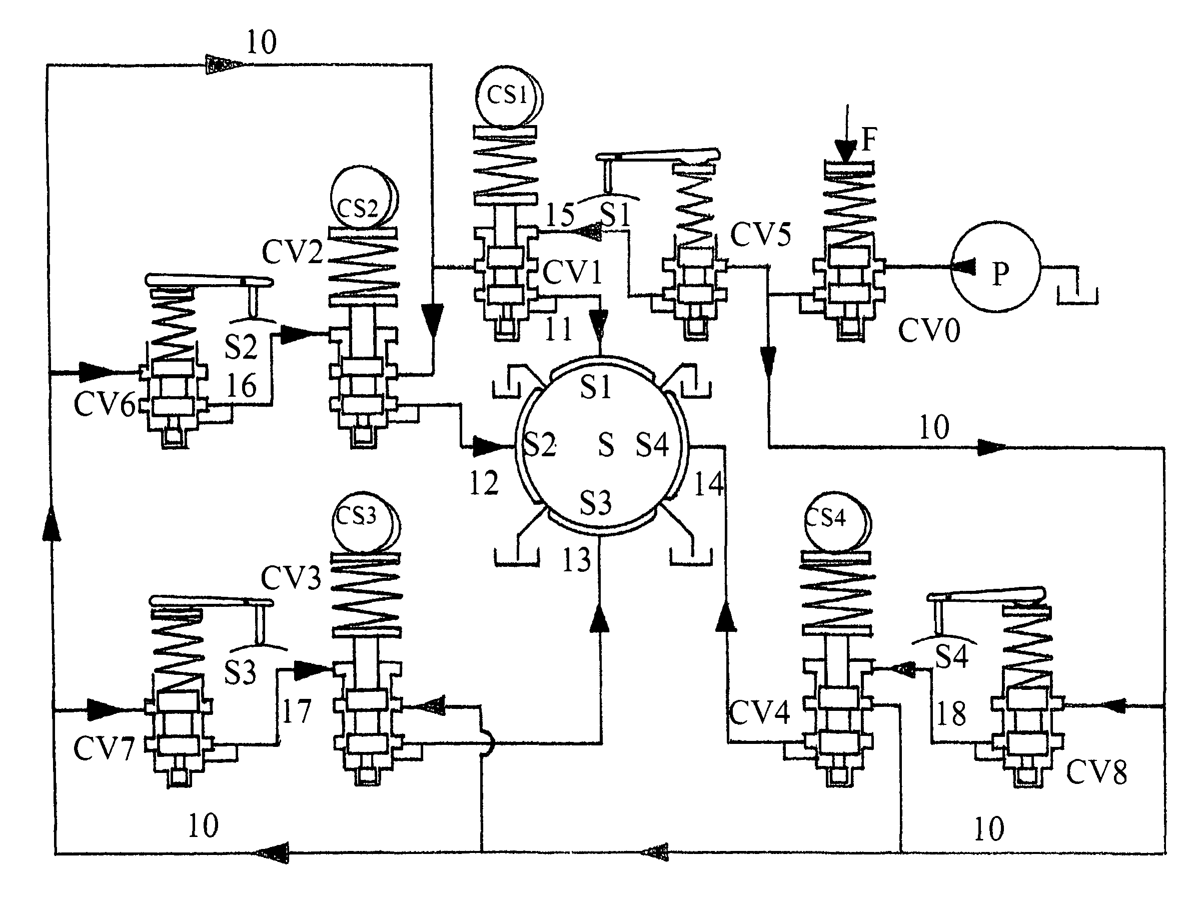
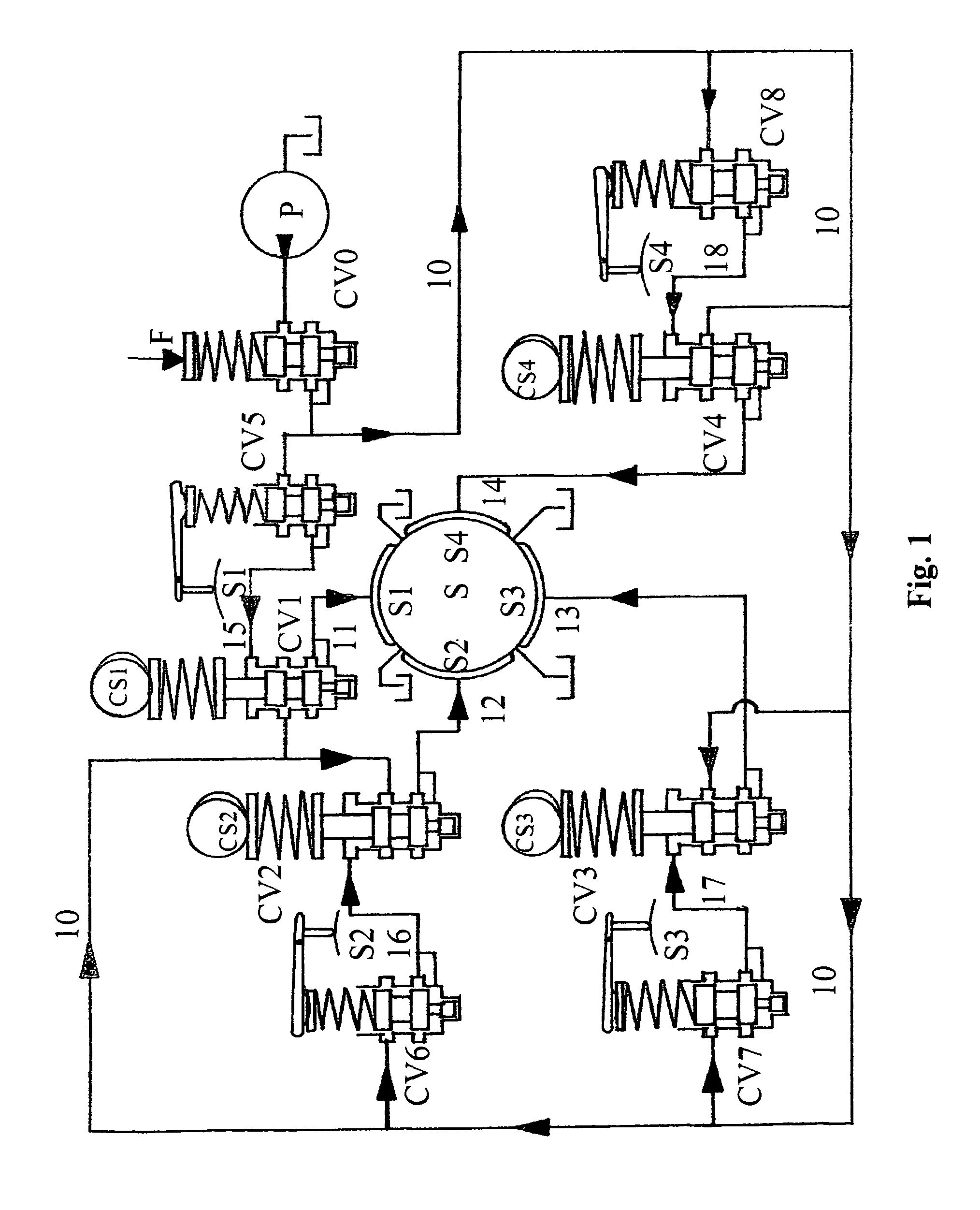
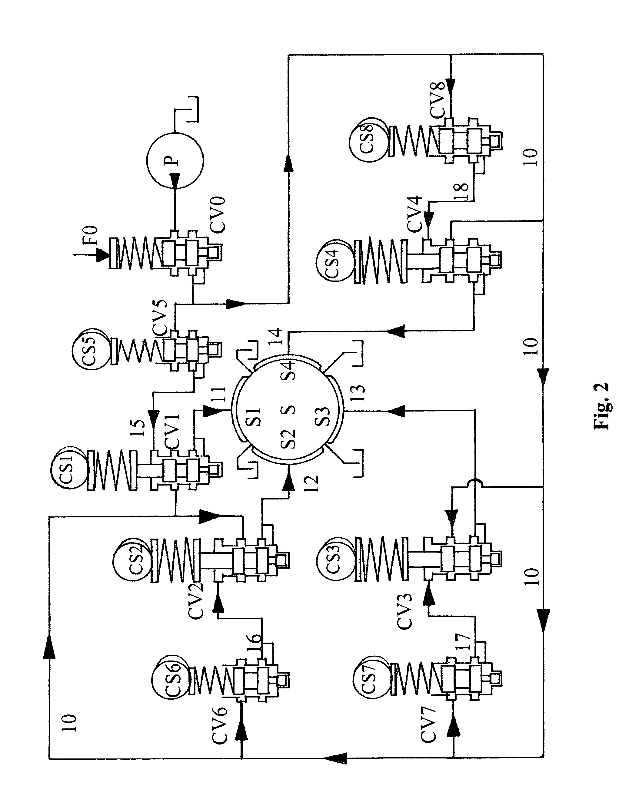
[0049]Another preferred embodiment of the invention, typically destined to support crankshafts of internal combustion engines, is depicted in FIG. 2. It is similar to above-described embodiment, the only major differences beeing an alternative destination of secondary control valves CV5, CV6, CV7 and CV8, presence of four additional cams CS5, CS6, CS7 and CS8, providing instantaneous setting of their respective secondary control valves, absence of a system for compensating random forces loading the shaft, and, in the case of four-stroke engines, an additional camshaft (not shown) rotating two times faster that the main shaft (see FIG. 2). These alterations results from a different application of the general method of the present invention. Namely, external force F loading the shaft is represented as the sum of two other forces, typically, in the case of application to an internal combustion engine, the mass force FM and the gas force FG, and these forces are treated separately, rath...

embodiment 2

[0051]Another preferred embodiment, destined to support a crankshaft of a large two-stroke engine shares a general scheme with the second preferred embodiment described above, but utilizes different decomposition of the mass force FM loading engine's crankshaft (see FIG. 2). Namely, force FM is decomposed into the first order force FM1 having the period of 360°, and the second order force FM2 having the period of 180°. Next force FM1 is combined with gas force FG (having the same period as force FM1) into one resulting force, which in turn is decomposed into its “horizontal” and “vertical” components. Both the components are presented as difference of two convex functions, say F2−F4 and F1−F3, and said functions are represented by cams CS1, CS2, CS3 and CS4 as described above. Force FM2 is decomposed into its “horizontal” and “vertical” components, each of the components is presented as the difference of two convex functions, say F6−F8 and F5−F7, which in turn are represented by cam...


PUM


Abstract

This invention relates to bearings, and more specifically is directed to active hydrostatic bearings destined for large heavily loaded reciprocating internal combustion engines, like ultra high compression ratio Diesel cycle engines, and homogeneous charge compression ignition (HCCI) and detonation engines working on stoichiometric fuel / air mixture. A fluid handling system therefore, method and apparatus are also disclosed.

Description

0. TECHNICAL FIELD OF THE INVENTION[0001]This invention relates to bearings, and more specifically is directed to active hydrostatic bearings destined for large heavily loaded reciprocating internal combustion engines, like ultra high compression ratio Diesel cycle engines, and homogeneous charge compression ignition (HCCI) and detonation engines working on stoichiometric fuel / air mixture. A fluid handling system therefore, method and apparatus are also disclosed.1. STATE OF THE ART AND BACKGROUND OF THE INVENTION[0002]Internal combustion reciprocating engines (Diesel and Otto cycle), most common prime movers in use, are responsible for substantial percentage of total hydrocarbon fuels expenditure and environment pollution. Their overall efficiency, i.e. the percentage of the energy contained in the fuel converted into the useful work, is in the range of 25-54%, wherein the upper bound of this range is approached only by large stationary or marine ultra long stroke crosshead Diesel ...

Claims


Application Information

Patent Timeline
Patent Type & Authority Patents(United States)
IPC IPC(8): F16C32/06
CPCF16C32/064
Inventor OLEDZKI, WIESLAW JULIAN
Owner OLEDZKI WIESLAW JULIAN
Why Eureka
Try Eureka