Terminating and connecting device

a technology of connecting device and solar module, which is applied in the direction of coupling contact member, coupling device connection, coupling/disassembly of coupling parts, etc., can solve the problems of difficulty, low mounting efficiency, and low effort in the mounting of known junction boxes on solar modules. achieve the effect of convenient and reliable mounting

Inactive Publication Date: 2013-09-03
PHOENIX CONTACT GMBH & CO KG
View PDF9 Cites 11 Cited by
  • Summary
  • Abstract
  • Description
  • Claims
  • Application Information

AI Technical Summary

Benefits of technology

[0013]Therefore, the object of the invention is to make available a terminating and connecting device for the electrical connection of an electrical device, especially of a solar module, which is made such that it can be easily and reliably mounted, and the mounting should take place preferably automated. Moreover, the junction box should be less sensitive to tolerances of the terminal leads and their position.

Problems solved by technology

The effort in the mounting of the known junction boxes on the solar modules is relatively high due to the manual connecting (soldering or screws) of the terminal leads to the terminal elements provided in the junction box.
In this junction box the electrical terminal of the terminal leads of the solar module is therefore connected with a relatively high manual effort.
However, the problem here is that the clamp spring must be opened by the flat ribbon when it is inserted in order to travel into the clamping site between the two spring legs.
Difficulties can arise in the known junction box when the terminal leads do not essentially project vertically from the solar module or when the junction box is not positioned accurately enough since it can happen that the terminal leads do not travel through the openings in the housing lower part between the clamping leg of the opened clamp springs and the contact section of the metal parts.

Method used


Image

  • Terminating and connecting device
  • Terminating and connecting device
  • Terminating and connecting device

Examples


Embodiment Construction

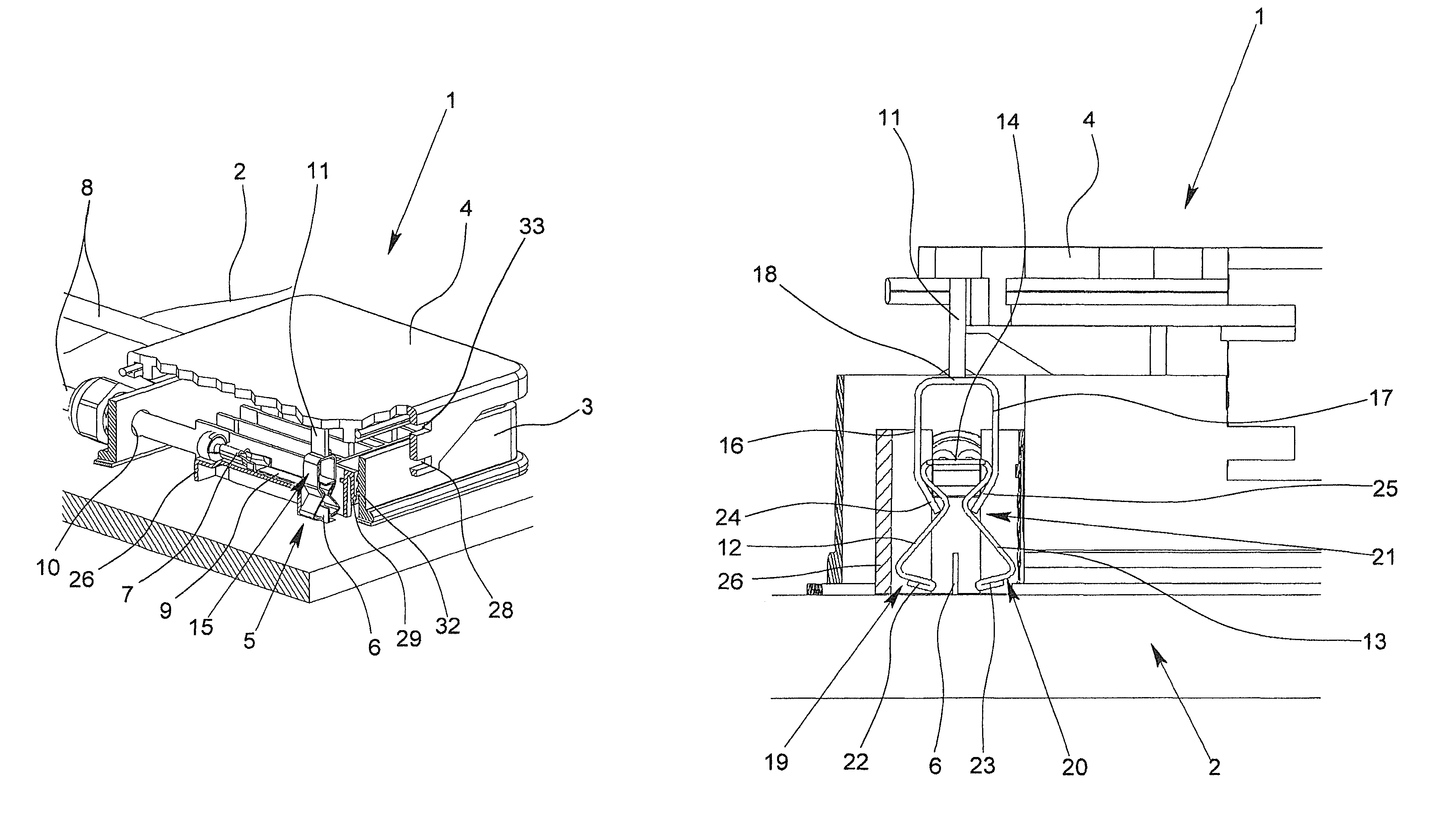
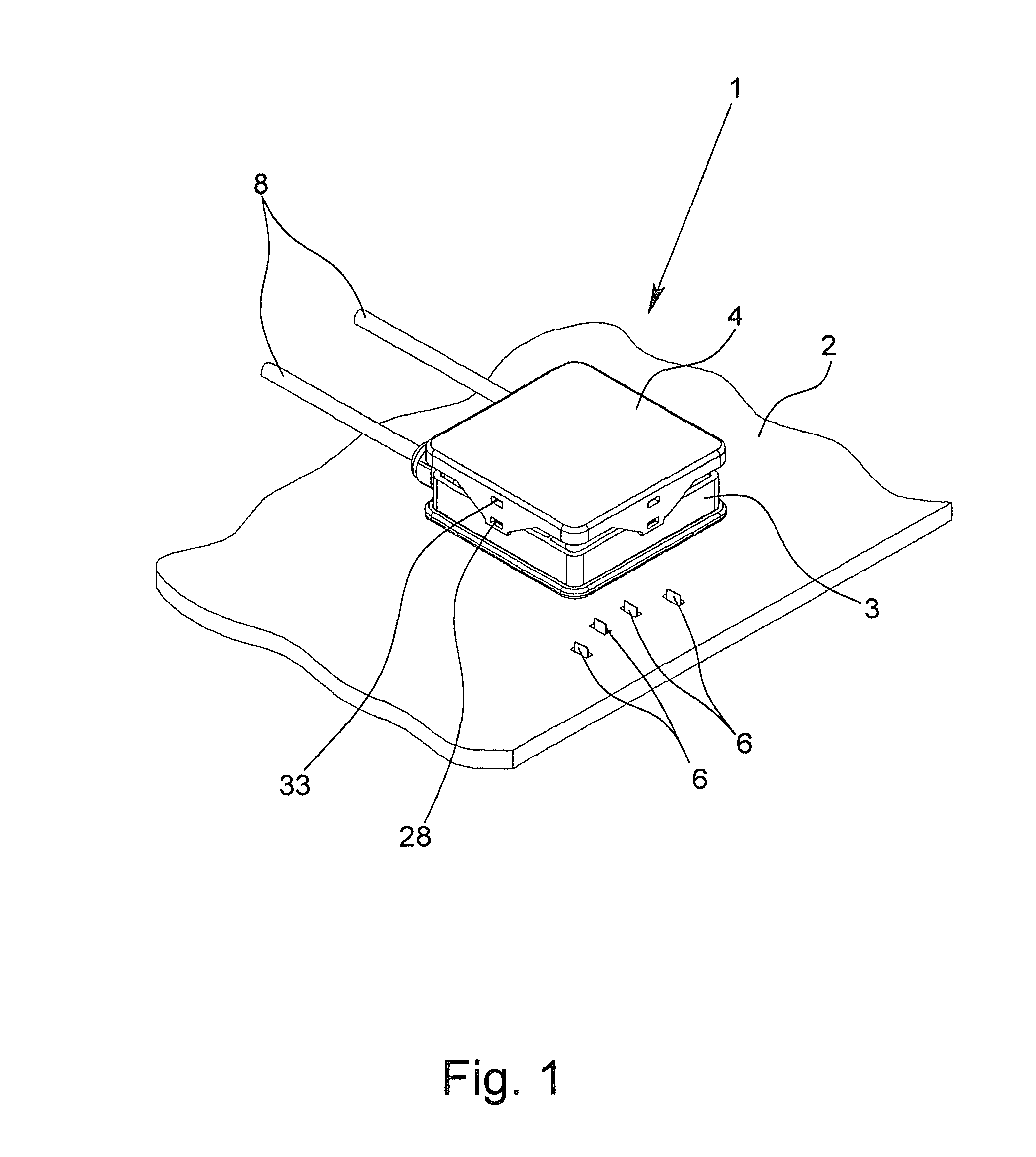
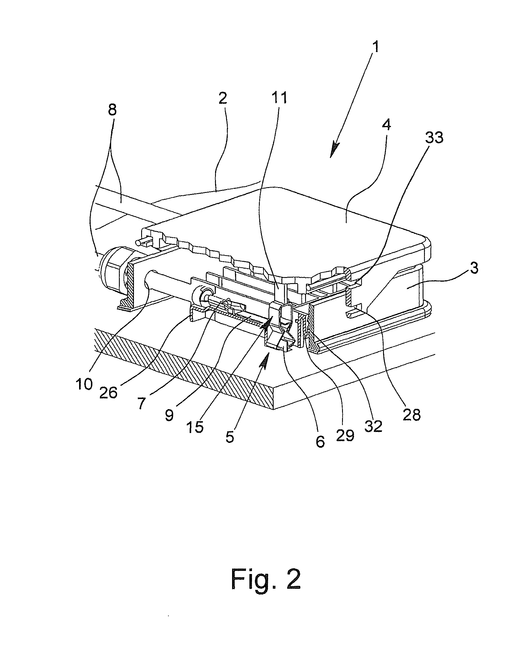
[0048]The figures show a terminating and connecting device 1 in accordance with the invention, or parts thereof, for the electrical connection of a solar module 2. The terminating and connecting device 1, which is also called a junction box below, has a housing which is formed of a housing lower part 3 and a housing upper part 4 and which can be seated with its housing lower part 3 on the solar module 2.

[0049]Within the housing lower part 3, there are several contact springs 5 which are used for making electrical contact with the terminal leads 6 of the solar module 2 which are made as flat conductors. Moreover, in the housing lower part 3 in the exemplary embodiment according to FIGS. 2, 3, 7, 10 and 11, there are two terminal elements 7 made as crimp terminals via which two external cables 8 are connected. Each contact spring 5 is connected via a respective metal part 9 to a respective terminal element 7 so that a terminal lead 6 contacted by means of the contact spring 5 can be c...


PUM


Abstract

A terminating and connecting device with a housing having a lower and upper housing parts, at least one contact spring for electrically contacting at least one terminal lead, at least one terminal element for connecting at least one cable, and at least one metal part for connecting the contact spring to a cable connected by the terminal element. The housing upper part has at least one actuating element and a contact spring. The contact spring has two contact legs connected by a back, and the lower housing part has a top spring has two spring legs and a back which connects the spring legs. When the housing upper part is pressed onto the housing lower part, the actuating element presses on the back of the top spring so that the top spring moves into a position such that the terminal lead is clamped between the contact legs.

Description

BACKGROUND OF THE INVENTION[0001]1. Field of the Invention[0002]The invention relates to a terminating and connecting device for electrical connection of an electrical device, especially a solar module, with a housing which has a housing lower part and a housing upper part, with at least one contact spring for electrical contacting of at least one terminal lead coming from the electrical device, with at least one terminal element located in the housing for connecting at least one cable and with at least one metal part via which the terminal lead contacted by the contact spring can be connected to a cable connected by the terminal element in an electrical conductive manner, the housing having at least one opening for inserting the cable, the contact spring, the terminal element and the metal part being assigned to the housing lower part and there being at least one actuating element on the housing upper part, and the contact spring, when the housing upper part is placed or pressed on...

Claims


Application Information

Patent Timeline
Patent Type & Authority Patents(United States)
IPC IPC(8): H01R13/62
CPCH01L31/02013H02S40/34H01R4/489Y02E10/50
Inventor EUSTERHOLZ, HELMUT
Owner PHOENIX CONTACT GMBH & CO KG
Why Eureka
Try Eureka