Toner cartridge

a technology of toner cartridges and seals, applied in the field of toner cartridges, can solve the problems of increasing the number of parts, difficult to pinch the seal member, and removing the seal member from the installation surface of the seal member, etc., and achieves the effect of easy removal, easy retention, and easy pinching

Active Publication Date: 2013-09-10
RICOH KK
View PDF12 Cites 6 Cited by
  • Summary
  • Abstract
  • Description
  • Claims
  • Application Information

AI Technical Summary

Benefits of technology

[0009]The present invention has been made in view of the above problems, and an object thereof is to provide a toner cartridge capable of being easily remove a seal member from a surface of a seal member installation without increasing a cost.
[0012]According to the present invention, a non-contact portion which is not in contact with the seal member installation surface is formed on the surface of the seal member that faces the seal member installation surface, so that there is a portion where is not in contact with the seal member installation surface on the surface of the seal member in the state where the seal member has been installed to the seal member installation surface. Further, a space is so provided in the engaging member so as to extend from the surface of the seal member on which the edge of the mouth portion is frictionally slid to the non-contact portion. In other words, a space for allowing pinching of the portion of the seal member that is not contact with the seal member installation surface is provided. As a result, when the seal member is removed from the seal member installation surface, it is possible to easily pinch, by a jig or finger, the portion of the seal member where is free from any contact with the seal member installation surface through the space. Since the portion of the seal member that is not in contact with the seal member installation surface can be easily retained in this manner, the seal member is easily removed from the seal member installation surface, and as a result, the time and effort required for removing the seal member from the seal member installation surface can be reduced.
[0013]Further, there is no need to disassemble the portion adjacent to the seal member installation surface in the engaging member for easy removal of the seal member from the seal member installation surface and, therefore, there is no need to increase the number of parts for making the engaging member easy to disassemble, thereby suppressing an increase in cost.
[0014]As described above, according to the present invention, the seal member can be easily removed from the seal member installation surface without increasing the cost.

Problems solved by technology

However, in the existing toner supply container, the seal member is brought into close contact with the seal member installation surface of the seal member installation portion or inner wall of the toner supply container, making it difficult to pinch the seal member when the seal member is removed from the seal member installation surface.
Thus, it takes time and effort to remove the seal member from the seal member installation surface.
However, the number of parts is increased to increase the cost of the toner supply container.[Patent Literature 1] Japanese Patent (JP-B) No. 3628539

Method used


Image

  • Toner cartridge
  • Toner cartridge
  • Toner cartridge

Examples


first embodiment

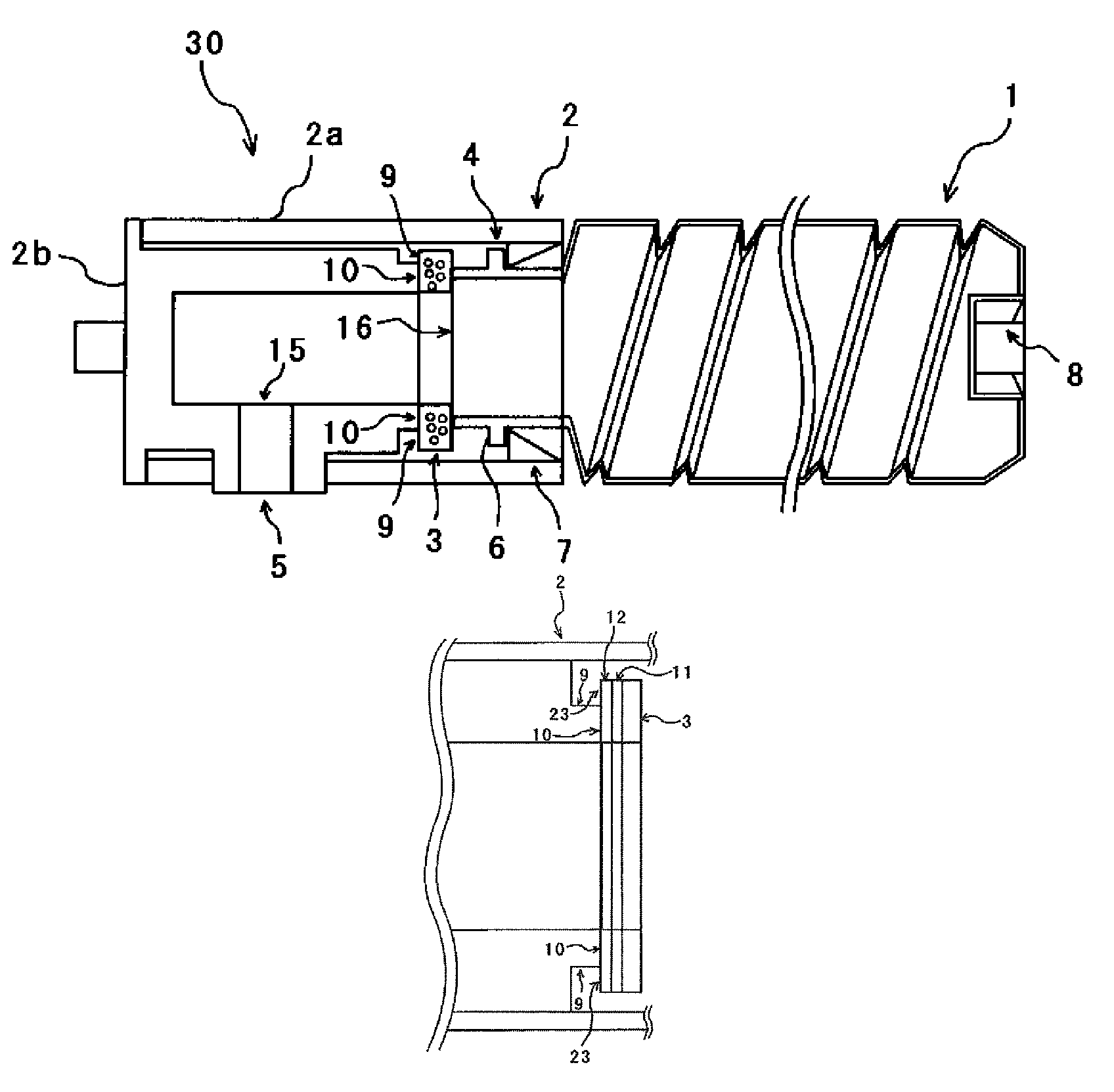
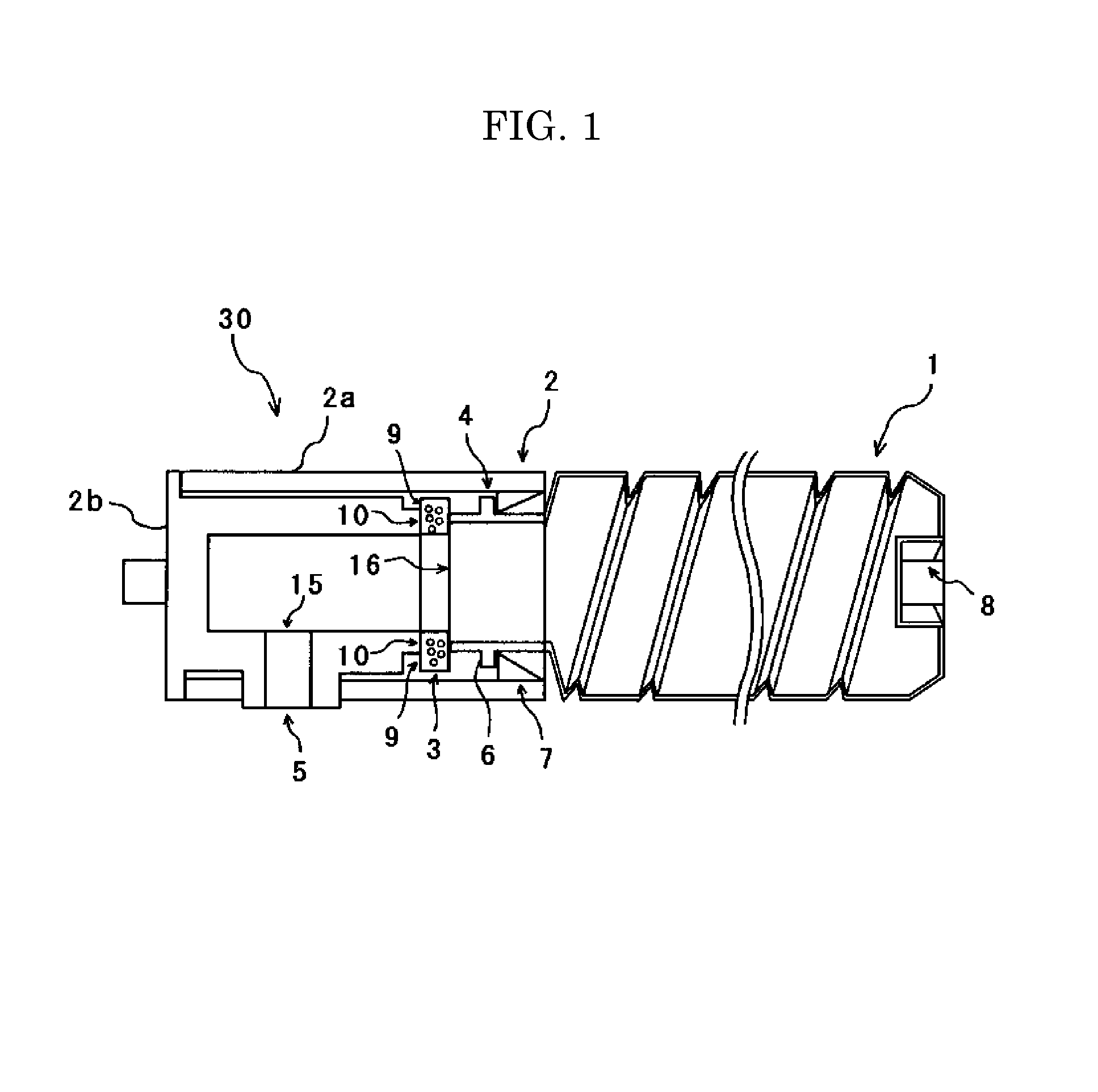
[0031]A toner container unit 30 shown in FIG. 1 which is a toner cartridge according to the present embodiment includes a container main body 1 and a supplying section 2. The container main body 1 is made of synthetic resin and includes a bottom portion, a circumferential portion, a shoulder portion, and a mouth portion. A drive force receiving portion 8 to be connected to drive force transmitting means of respective developing sections is formed at the bottom portion which is the attaching-side end portion of the container main body 1 to be attached to a developing unit of an image forming apparatus such as a copying machine, and the supplying section 2 is attached to a mouth portion 16 which is the other side end portion of the container main body 1. A spiral groove is formed in the inner and outer peripheral surfaces of the side peripheral portion of the container main body 1. A container ring 6 protrudes outward from the leading end outer circumferential surface of the mouth por...

second embodiment

[0057]A configuration of the toner container unit 30 according to the present embodiment is substantially the same as the configuration of the toner container unit 30 according to the first embodiment, and hence, the description will be made of only a characteristic point.

[0058]In the present embodiment, as shown in FIG. 14, an inner diameter F of the seal member 3 is made smaller than an inner diameter G of a seal member installation portion 21. When the inner diameter F of the seal member 3 is made smaller than the inner diameter G of the seal member installation portion 21, a non-contact portion 24 which is a portion where the seal member 3 is not in contact with a seal member installation surface 22 of the seal member installation portion 21 is formed on the inner circumferential side of the ring-shaped seal member 3. Further, as shown in FIG. 14, a space (at least the area enclosed by dashed line in FIG. 14) for easy pinching of the seal member 3 is provided around the seal mem...


PUM


Abstract

A toner cartridge contains a toner container including an opening and configured to contain a toner. An engaging member includes a ring-shaped seal member disposed on a seal member installation surface. The engaging member is engaged with the toner container to cover the opening and rotatably mounted to the toner container while an edge of the opening is frictionally slid on a surface of the seal member. The toner container is configured to convey the toner into the engage member through the opening and discharge the toner therefrom as the toner container is rotated. The seal member includes a non-contact portion at a surface thereof facing the installation surface and being free from any contact with the installation surface so that the engage member includes a space extending from the surface of the seal member where the edge of the opening is frictionally slid to the non-contact portion.

Description

TECHNICAL FIELD[0001]The present invention relates to a toner cartridge for supplying toner to a developing section in an image forming apparatus such as a printer, a facsimile, and a copying machine.BACKGROUND ART[0002]There has widely been used an image forming apparatus, such as a copying machine, a facsimile, and a printer, that uses an electrophotographic system to form an electrostatic latent image on a photoconductive member, develop the electrostatic latent image using a toner which is a developer, and transfer an obtained toner image onto a transfer sheet. In order to enable continuous image forming operation, the image forming apparatus of this type has a mechanism in which a toner is supplied to a developing section in such a manner as to prevent the developing section to run out of the toner.[0003]As a method that supplies a toner to the developing section of an image forming apparatus, there is known the method in which a toner supply container containing a toner in the...

Claims


Application Information

Patent Timeline
Patent Type & Authority Patents(United States)
IPC IPC(8): G03G15/08
CPCG03G15/0872G03G15/0881G03G2215/0668
Inventor KAWAMURA, YOSHIHIDEHASEGAWA, MASASHI
Owner RICOH KK
Why Eureka
Try Eureka