Management computer for setting configuration information of node

a management computer and configuration information technology, applied in the field of network management, can solve the problems of reducing the availability of the network, limiting the extent to which these protocols are effective for recovery from failures, etc., and achieve the effect of less workload

Inactive Publication Date: 2013-09-10
ALAXALA NETWORKS
View PDF11 Cites 0 Cited by
  • Summary
  • Abstract
  • Description
  • Claims
  • Application Information

AI Technical Summary

Benefits of technology

[0016]Specifically, the network administrator has to set the inter-switch connection relation and VLANs for all of the above switches. This means that the larger the network scale, the more switches need settings change by the network administrator. An increase in network scale therefore increases the workload of the network administrator, who will find it difficult to change the settings of switches correctly and timely.
[0017]This invention has been made in view of the above, and it is a first object of this invention to facilitate the introduction of a redundancy configuration to a large-scale network by reducing the workload of the administrator of the network that is required to change the settings of switches.
[0019]It is a second object of this invention to reduce switch setting errors in a large-scale network when the network configuration is changed by reducing the workload of the administrator of the network that is required to change the settings of switches.
[0021]According to a mode of this invention, less workload is required of the administrator of a network to set switches when the network is changed into a network that has redundancy.

Problems solved by technology

This lowers the availability of the network significantly since communication cannot be held over the network until the failed network device is replaced with a functioning one.
The extent to which these protocols are effective for recovery from a failure is limited to adjacent (interconnected) network devices.

Method used


Image

  • Management computer for setting configuration information of node
  • Management computer for setting configuration information of node
  • Management computer for setting configuration information of node

Examples


first embodiment

[0061]A first embodiment of this invention will be described below with reference to FIGS. 1 to 33.

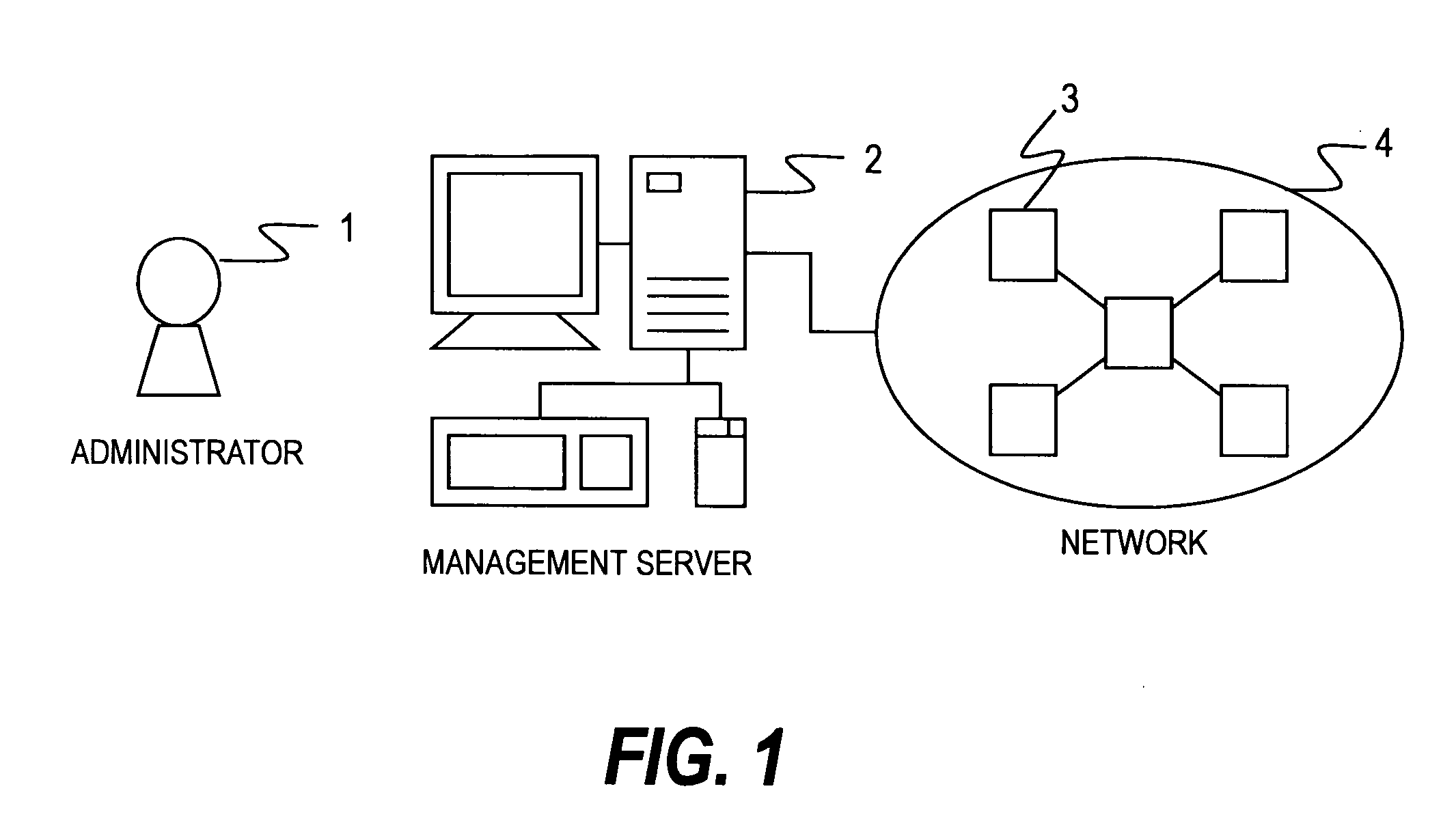
[0062]FIG. 1 is a diagram showing the configuration of a computer system according to the first embodiment of this invention.

[0063]This computer system contains a management server 2 and a network 4, which is managed by the management server 2.

[0064]An administrator 1 of the network 4 can know the configuration of the network 4 through an input / output device of the management server 2, on which the configuration of the network 4 is displayed. The administrator 1 can also enter an instruction for providing the network 4 redundancy to the input / output device of the management server 2.

[0065]The management server 2 is connected to the network 4 to receive link information, which indicates the connection relation between network devices 3. The management server 2 sets the settings of the network devices 3 using a protocol for setting the network devices 3. The network devices 3 are, for ex...

second embodiment

[0269]A second embodiment of this invention describes how the management server 2 designs the settings of the switches 300 automatically in the case where the administrator 1 selects two of the switches 300 constituting a network as the switches 300 that serve as redundancy switches.

[0270]The second embodiment will be described with reference to FIGS. 34 and 35.

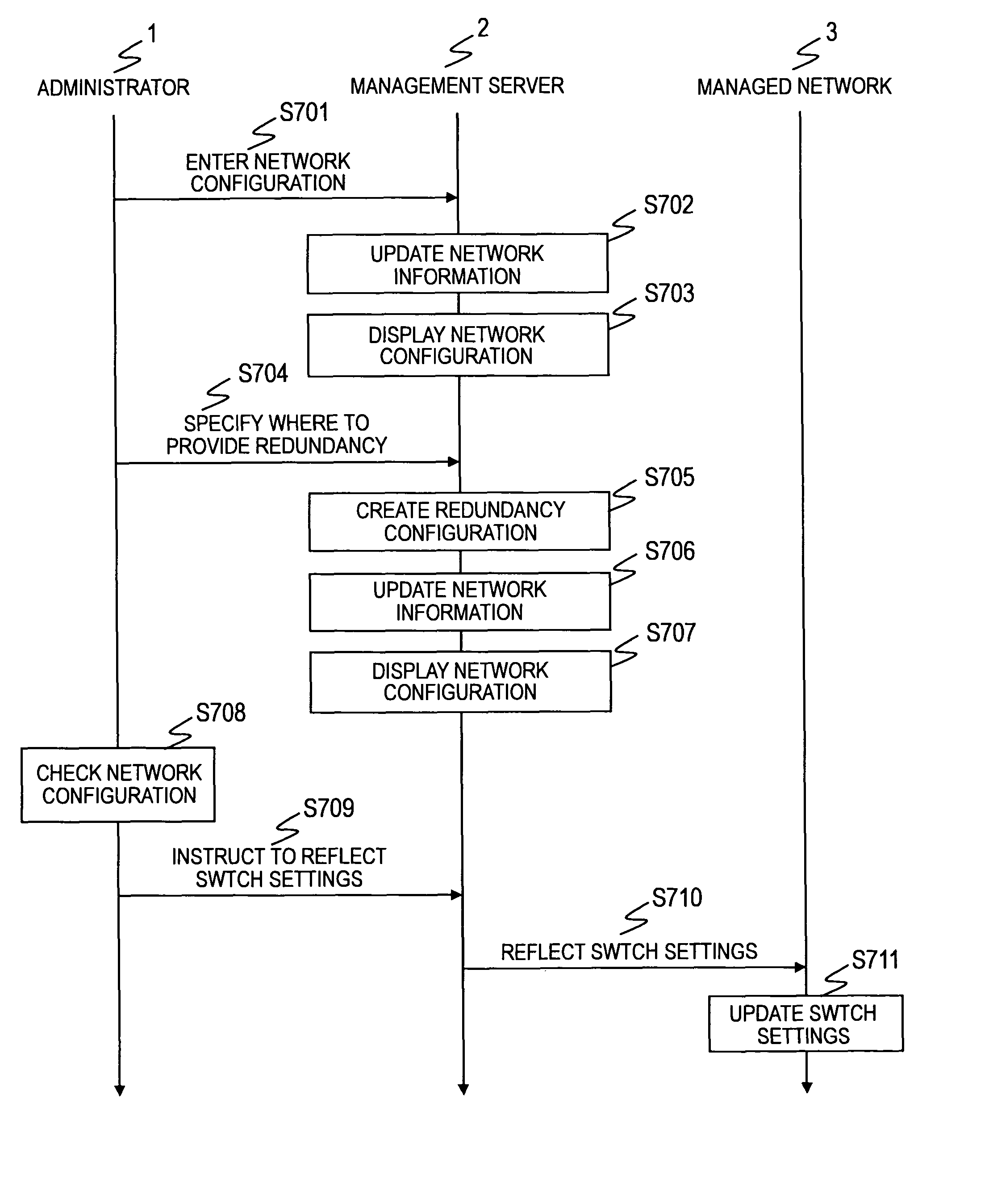
[0271]FIG. 34 is a sequence diagram of network designing in the management server 2 when two of the switches 300 constituting a network are selected as the switches 300 that serve as redundancy switches according to the second embodiment of this invention.

[0272]First, as in S701 of FIG. 4, the administrator 1 enters a network configuration to the management server 2 (S3701).

[0273]Subsequently, as in S702 of FIG. 4, based on the entered network configuration, the management server 2 updates network information managed in the VLAN information management table 212, the port information management table 213, and the redundant sys...

third embodiment

[0299]A third embodiment of this invention will be described next with reference to FIG. 36.

[0300]In the third embodiment, the management server 2 creates redundancy switch settings based on link information that is sent from the new switch 300 when the new switch 300 is newly added to the network 4.

[0301]FIG. 36 is a sequence diagram of network designing in the management server 2 according to the third embodiment of this invention.

[0302]S3901 to S3903 and S3905 to S3912 are the same as S3701 to S3703 and S3705 to S3712 described in the second embodiment with reference to the flow chart of FIG. 34, and the description will not be repeated.

[0303]In S3904, the new switch 300 sends link information to the management server 2 when connected to another switch 300. The switch 300 to which the new switch 300 is connected will be referred to as a connected switch 300.

[0304]The link information contains the identifier of the new switch 300, the identifier of one of the ports of the new swit...


PUM


Abstract

Provided is a management computer which reduces the workload of an administrator of a network in setting node when the normal network is changed to a network with redundancy. The management computer manages a plurality of nodes that constitute a network accommodating VLANs. The plurality of nodes include a first node and a second node which make a redundancy pair and which divides the network into an active path and a standby path. The management computer stores port management information showing connection relations for respective nodes and identifiers of VLANs allocated to ports of the nodes, and creates the redundancy pair by updating the port management information of the first node such that a VLAN allocated to one of ports of a connected node that is connected to the first node is allocated to one of ports of the first node that is connected to the connected node.

Description

CLAIM OF PRIORITY[0001]The present application claims priorities from Japanese patent application P2007-118360 filed on Apr. 27, 2007, and Japanese patent application P2007-339630 filed on Dec. 28, 2007, the content of which are hereby incorporated by reference into this application.BACKGROUND OF THE INVENTION[0002]This invention relates to a management computer for network management and, more particularly, to a management computer that automatically sets switches constituting a network.[0003]The networking of business operations (including mission-critical applications) in a corporation has lately become increasingly common, which has created a demand for improved network availability.[0004]In a conventional network, a failure in a network device such as a switch or a router is dealt with by the administrator of the network by manually replacing the failed network device. This lowers the availability of the network significantly since communication cannot be held over the network ...

Claims


Application Information

Patent Timeline
Patent Type & Authority Patents(United States)
IPC IPC(8): G06F15/173
CPCH04L12/66
Inventor OKITA, HIDEKIOZAWA, YOJI
Owner ALAXALA NETWORKS
Why Eureka
Try Eureka