Wireline pressure setting tool and method of use

a technology of setting tool and wireline, which is applied in the direction of wellbore/well accessories, fluid removal, domestic applications, etc., can solve the problems of personal exposure to potentially hazardous chemicals, many disadvantages inherent in the use of explosive setting tools, and the danger of depressurizing the setting tools

Active Publication Date: 2013-09-17
CARISELLA JAMES V
View PDF17 Cites 15 Cited by
  • Summary
  • Abstract
  • Description
  • Claims
  • Application Information

AI Technical Summary

Problems solved by technology

Not only is the depressurization of the setting tool dangerous, but it also exposes personal to potentially hazardous chemicals that result from the combustion of the pyrotechnic.
While many procedures have been developed to minimize the risks associated with an explosive setting tool, many disadvantages inherent in the use of an explosive setting tool still remain.
Explosives are dangerous to handle and difficult to store and maintain on the job site.
Moreover, the use of explosives requires that the firing chamber of the tool be cleaned after every use, thereby adding to the maintenance requirements of the tool.

Method used


Image

  • Wireline pressure setting tool and method of use
  • Wireline pressure setting tool and method of use
  • Wireline pressure setting tool and method of use

Examples


Embodiment Construction

[0022]As used herein, “a” or “an” means one or more than one. Additional, distal refers to the end of the element closest to the setting mandrel of the setting tool and proximal end refers to the end of the element closest to the firing head of the setting tool.

[0023]The methods and apparatus of the present invention will now be illustrated with reference to FIGS. 1A through 9. It should be understood that these are merely illustrative and not exhaustive examples of the scope of the present invention and that variations which are understood by those having ordinary skill in the art are within the scope of the present invention.

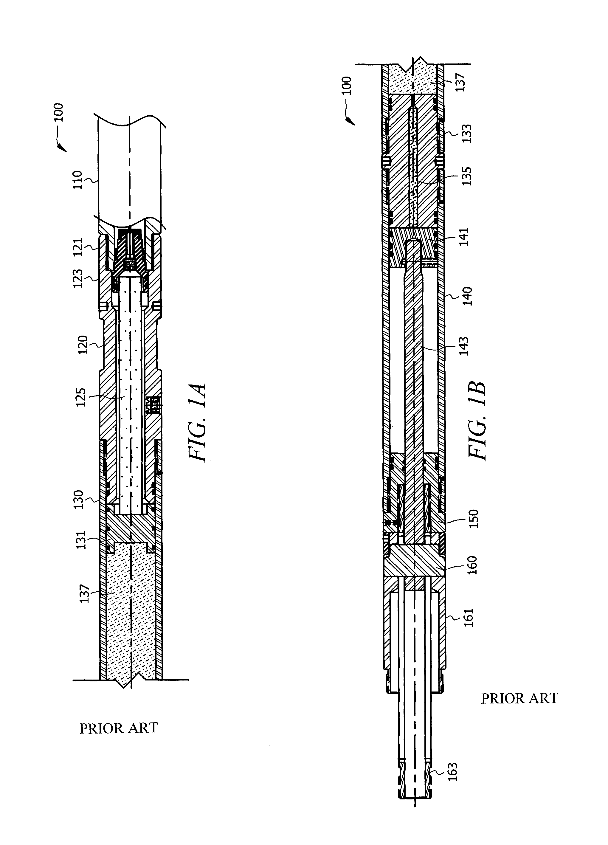
[0024]Turning now to FIGS. 1A and 1B, a prior art explosive setting tool 100 is shown. The explosive setting tool includes firing head 110, pressure chamber 120, upper cylinder 130, lower cylinder 140, cylinder head 150, and crosslink 160. Explosives or pyrotechnics are typically installed in pressure chamber 120. Typical prior art explosive setting tools incl...


PUM

PropertyMeasurementUnit
pressureaaaaaaaaaa
cracking pressureaaaaaaaaaa

Abstract

A method and apparatus for retro-fitting an explosive setting tool to a non-explosive setting tool is provided to eliminate the use of pyrotechnics when setting auxiliary tools. An explosive setting tool is retro-fitted by removing the pyrotechnic elements of the tool and replacing them with a conversion assembly including a hydraulic pump, thus converting the explosive tool into a non-explosive tool. The hydraulic pump provides the energy necessary to set the auxiliary tool. Once the auxiliary tool has been set, the non-explosive setting tool can be brought to the surface and reset using a resetting tool.

Description

TECHNICAL FIELD[0001]This invention relates to a setting tool for use in a wellbore, and a method of using a setting tool.BACKGROUND OF THE INVENTION[0002]Subterranean well tools are introduced or carried into a subterranean oil or gas well on a conduit, such as wire line, electric line, continuous coiled tubing, threaded work string, or the like, for engagement at a pre-selected position within the well along another conduit having an inner smooth wall, such as casing. These tools include devices such as expandable elastomeric, permanent or retrievable plugs, packers, ball-type and other valves, injectors, perforating guns, tubing and casing hangers, cement plug dropping heads, and other devices typically encountered during the drilling, completion, or remediation of a subterranean well. Such devices and tools will hereafter collectively be referred to as “auxiliary tools.” The auxiliary tool is typically set and anchored into position within the casing such that movements in vario...

Claims


Application Information

Patent Timeline
Patent Type & Authority Patents(United States)
IPC IPC(8): E21B23/00E21B43/00E21B29/02
CPCE21B23/04Y10T29/49716E21B23/0412
Inventor CARISELLA, JAMES V.
Owner CARISELLA JAMES V
Why Eureka
Try Eureka