Method and system for etching a diaphragm pressure sensor

a diaphragm pressure sensor and etching technology, applied in the field of pressure sensing devices and techniques, can solve the problems of insufficient etch depth control, affecting device performance and manufacturing yield, and unable to produce satisfactory yields for high sensitivity devices, etc., to achieve enhanced diaphragm structure, high strain/stress, and optimized diaphragm thickness and siz

Active Publication Date: 2013-09-17
HONEYWELL INT INC
View PDF3 Cites 0 Cited by
  • Summary
  • Abstract
  • Description
  • Claims
  • Application Information

AI Technical Summary

Benefits of technology

[0009]The aforementioned aspects and other objectives and advantages can now be achieved as described herein. A method for etching a diaphragm pressure sensor based on a hybrid anisotropic etching process is disclosed herein. A substrate (e.g., a silicon wafer) with an epitaxial layer can be etched utilizing an etching process (e.g., a deep reactive ion etching) in order to form a rectangular diaphragm at a selective portion of the substrate. The diaphragm edges can be oriented at an angle (e.g., 45 degree) with respect to the <110> direction on a (100) substrate in order to avoid an uncertain beveled portion in a stress / strain field of the diaphragm. The diaphragm can be further etched utilizing an etch finishing process (e.g., KOH etching) to create an anisotropic edge portion on the major areas of the diaphragm and optimize the thickness and size of the diaphragm. Such an approach provides an enhanced diaphragm structure with respect to a wide range of pressure sensor applications.
[0010]The diaphragm can be oriented at 45 degree angle with respect to the substrate so that the non-beveled edge receives high strain / stress due to the applied pressure, while the corners where a bevel might form, receive the least stress / strain of the applied pressure. One or more piezoelectric resistors can be located on the diaphragm of the substrate in order to measure a stress / strain due to the applied pressure on the diaphragm. The orientation of the diaphragm creates the anisotropic etch edge on the regions where the piezoresistors are located and permit control of the final edge by designing the etch feature relative to a longest etch time required to remove any DRIE etch non-uniformity in depth. The uncertain beveling portion formed in the corners of the diaphragm can vary with an amount of difference between the DRIE surface uniformity and etch rate. Such an approach can be effectively employed to construct a simple, cost-effective, and pressure sensitive sensor with good diaphragm thickness control while maintaining minimum chip size.

Problems solved by technology

As a result, a chip for forming the diaphragm must be larger and therefore fewer die are produced per wafer, which crucially affects the device performance and manufacturing yield.
One of the problems associated with such prior art approach is that the etch depth control is not enough to produce a satisfactory yield for high sensitivity devices.

Method used


Image

  • Method and system for etching a diaphragm pressure sensor
  • Method and system for etching a diaphragm pressure sensor
  • Method and system for etching a diaphragm pressure sensor

Examples


Embodiment Construction

[0021]The particular values and configurations discussed in these non-limiting examples can be varied and are cited merely to illustrate at least one embodiment and are not intended to limit the scope thereof.

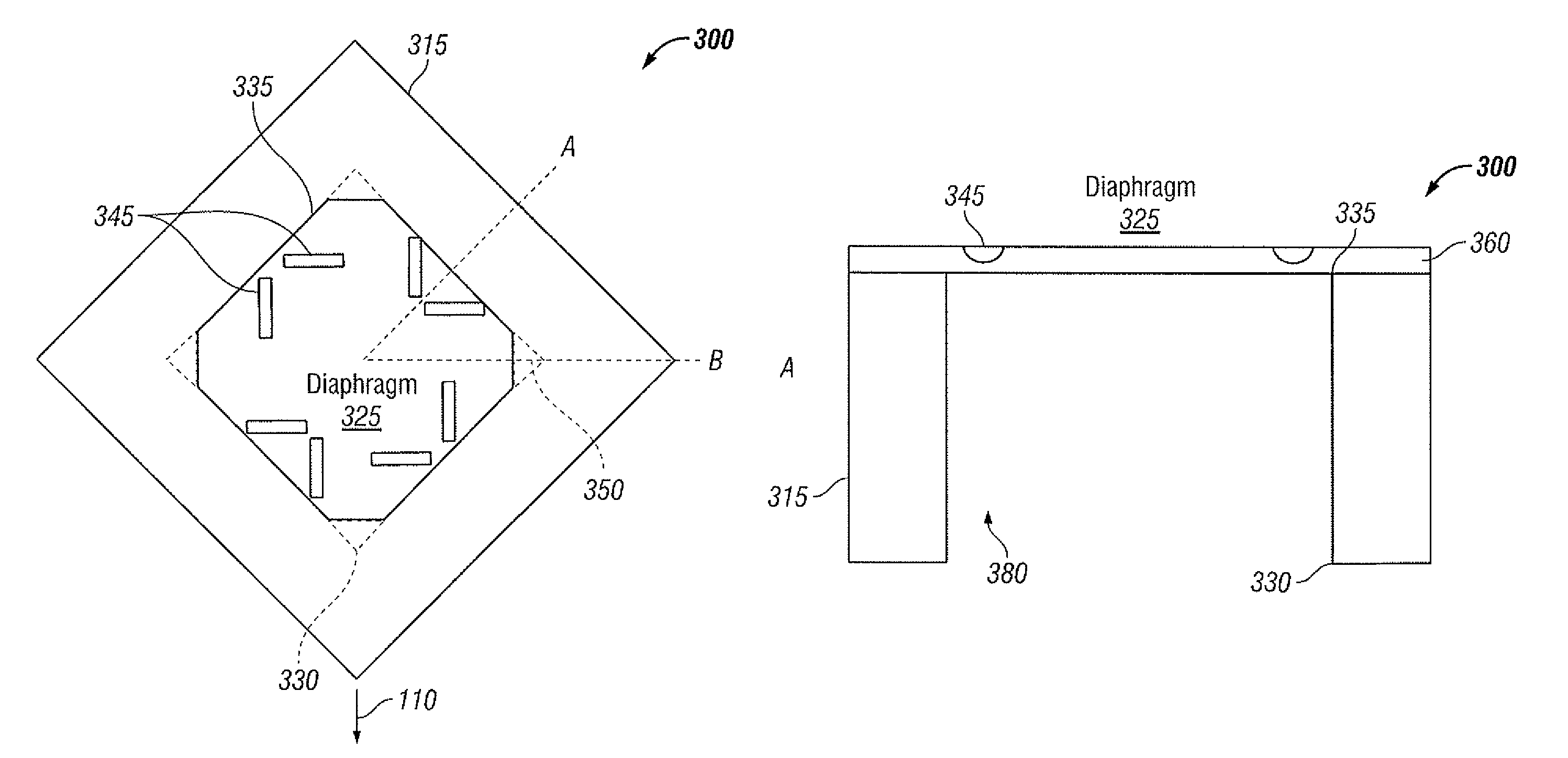
[0022]FIG. 5 illustrates a top view of a diaphragm pressure sensor 300 fabricated at an angle utilizing a hybrid anisotropic etching process, in accordance with the disclosed embodiments. The diaphragm pressure sensor 300 can be generally employed in varying sensing application to measure an applied pressure. The pressure sensor 300 includes a diaphragm 325 etched on a substrate 315 (e.g., a silicon wafer with (100) crystallographic orientation) via the hybrid etching process. The hybrid etching process combines a DRIE (Deep Reactive Ion Etching) etching process and a KOH (Potassium Hydroxide) etch finishing process. Note that the substrate 315 may be configured from a material such as, for example, a silicon material. It can be appreciated, of course, that other types of mater...


PUM


Abstract

A method for etching a diaphragm pressure sensor based on a hybrid anisotropic etching process. A substrate with an epitaxial etch stop layer can be etched utilizing an etching process in order to form a diaphragm at a selective portion of the substrate. The diaphragm can be oriented at an angle (e.g., 45 degree) with respect to the substrate in order to avoid an uncertain beveled portion in a stress / strain field of the diaphragm. The diaphragm can be further etched utilizing an etch finishing process to create an anisotropic edge portion on the major areas of the diaphragm and optimize the thickness and size of the diaphragm. Such an approach provides an enhanced diaphragm structure with respect to a wide range of pressure sensor applications.

Description

TECHNICAL FIELD[0001]Embodiments are generally related to pressure sensing devices and techniques. Embodiments are also related to etching techniques. Embodiments are additionally related to the etching of a pressure sensor diaphragm.BACKGROUND OF THE INVENTION[0002]Pressure sensors are employed in a wide range of pressure sensing applications in order to convert change in pressure of a fluid (e.g., gas, water etc) into a corresponding electric signal. Such pressure sensors typically include a diaphragm, a transmitter and a pressure detection unit to measure pressure of the fluid. The diaphragm includes a receiving surface for receiving the pressure with respect to the fluid and adding load to the transmitter. The diaphragm can be formed by etching a portion of wafer (e.g., silicon) with a desired thickness. The sensitivity of a piezoresistive based pressure sensor is highly dependent on the final diaphragm thickness and the position of a resistor relative to the edge of the diaphra...

Claims


Application Information

Patent Timeline
Patent Type & Authority Patents(United States)
IPC IPC(8): H01L21/00
CPCG01L9/0042G01L9/0054
Inventor HIGASHI, ROBERT
Owner HONEYWELL INT INC
Why Eureka
Try Eureka