Power converter system and methods of operating a power converter system

a power converter and power technology, applied in the field of power systems, can solve problems such as unsatisfactory voltage amplitude generation within the power converter, and achieve the effect of increasing the duty cycl

Active Publication Date: 2013-09-17
GENERAL ELECTRIC CO
View PDF16 Cites 31 Cited by
  • Summary
  • Abstract
  • Description
  • Claims
  • Application Information

AI Technical Summary

Benefits of technology

[0005]In another embodiment, a method of operating a power converter system is provided that includes electrically coupling a solar panel array to a converter including a plurality of converter switches, wherein the converter is coupled to an inverter including a plurality of inverter switches. The method also includes gradually increasing a duty cycle of the plurality of inverter switches, gradually increasing a duty cycle of the plurality of converter switches, and supplying power from the solar panel array to an electrical distribution network.
[0006]In yet another embodiment, a method of operating a power converter system including an inverter and a converter is provided. The method includes operating a plurality of converter switches at a first converter duty cycle, wherein the plurality of converter switches are included within the converter, and wherein the converter is coupled to a solar panel array. The method also includes operating a plurality of inverter switches at a first inverter duty cycle, wherein the plurality of inverter switches are included within the inverter. The method also includes gradually reducing a duty cycle of the plurality of converter switches, gradually reducing a duty cycle of the plurality of inverter switches, and electrically decoupling the solar panel array from the converter.

Problems solved by technology

If, however, the power converter is disabled (i.e., “shut down”) or enabled (i.e., “started up”) quickly, an undesired voltage amplitude may be generated within the power converter.

Method used


Image

  • Power converter system and methods of operating a power converter system
  • Power converter system and methods of operating a power converter system
  • Power converter system and methods of operating a power converter system

Examples


Embodiment Construction

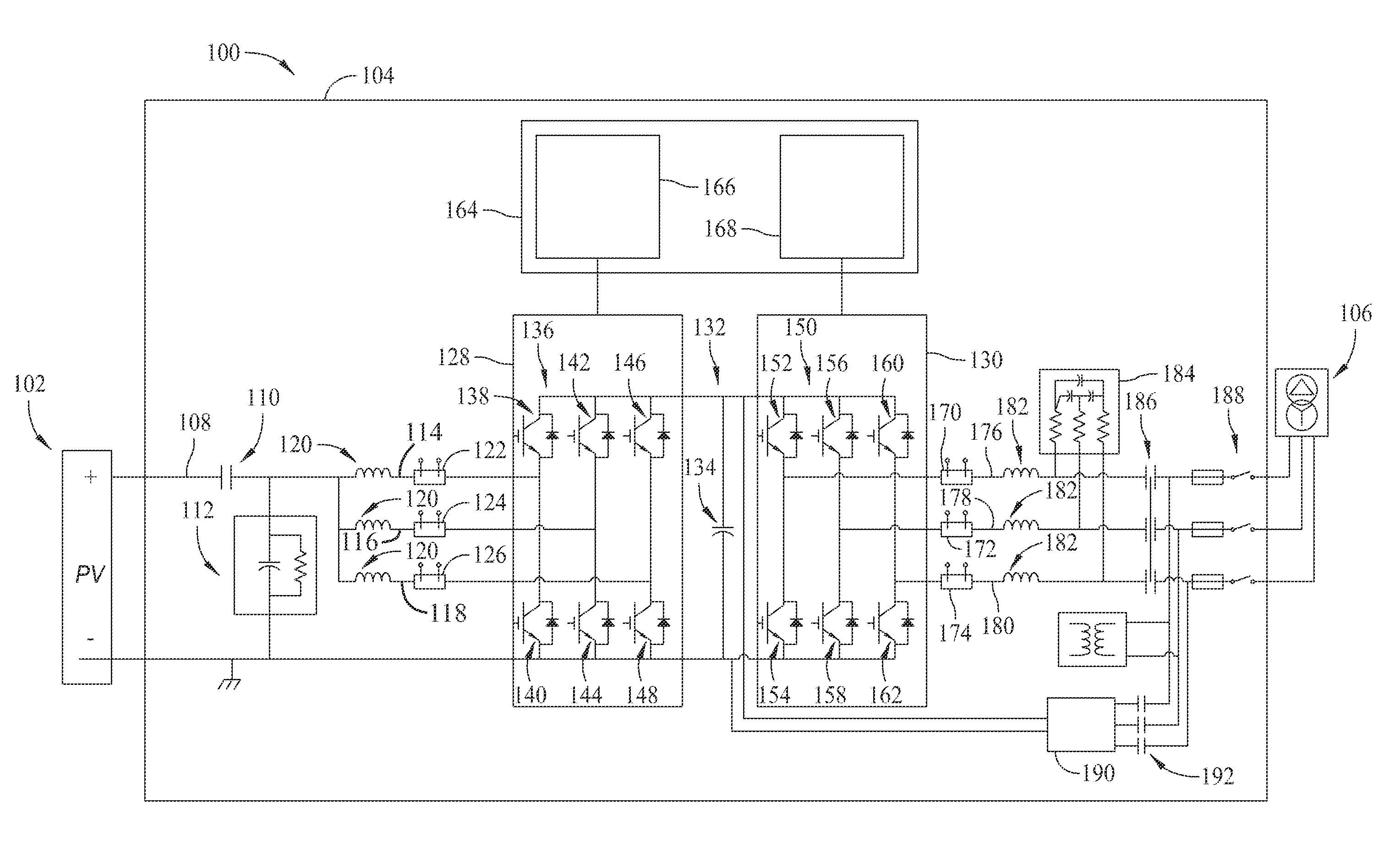
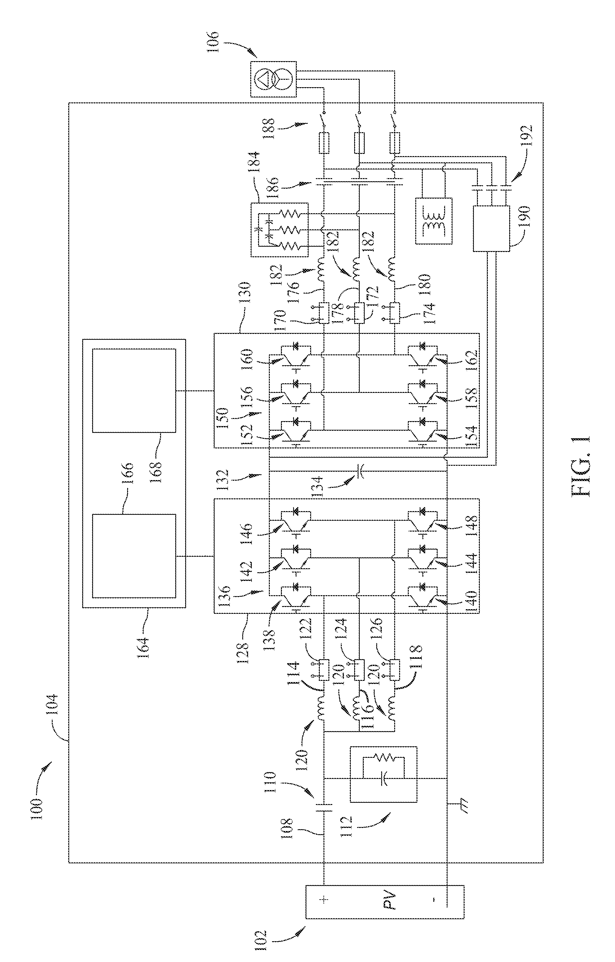
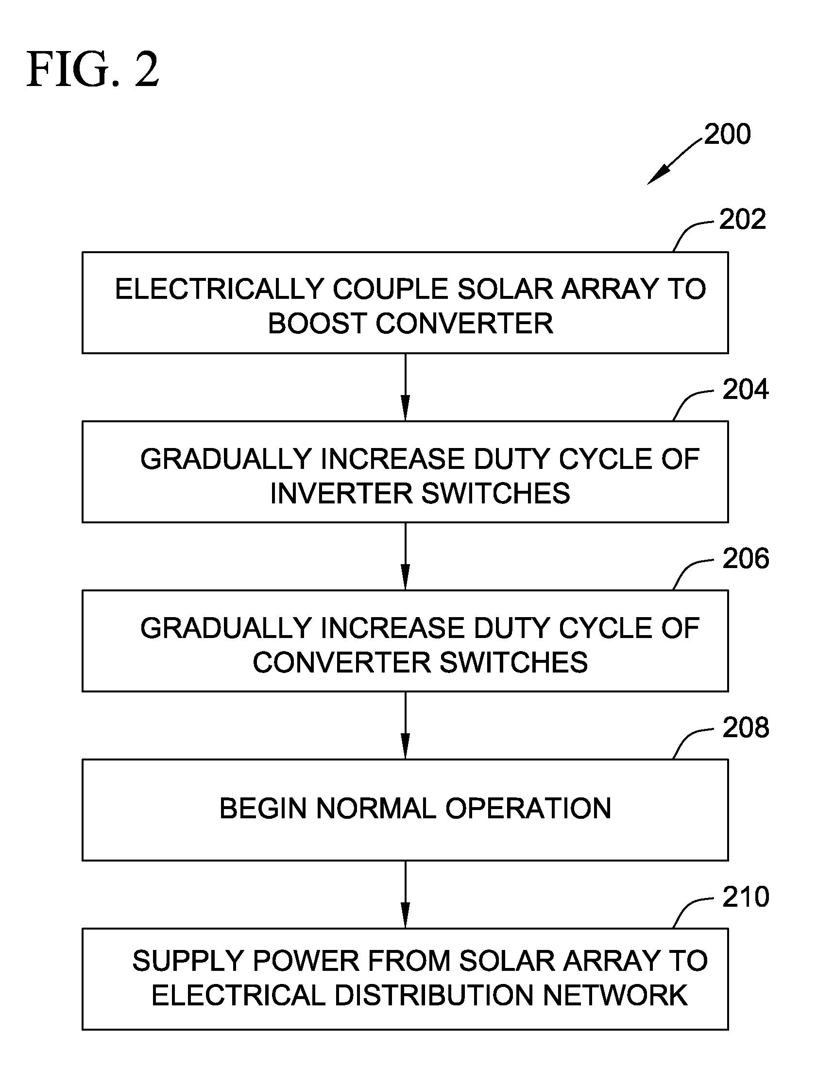
[0010]As described herein, a power generation system includes a power converter and at least one power generation unit, such as a solar array. The power converter includes a boost converter coupled to the solar array, and an inverter coupled to the boost converter by a DC bus. The inverter is coupled to an electrical distribution network for supplying electrical energy to the network. A converter controller controls the operation of the boost converter, and an inverter controller controls the operation of the inverter. The converter controller adjusts a duty cycle of a plurality of converter switches within the converter, and the inverter controller adjusts a duty cycle of a plurality of inverter switches within the inverter. If a shutdown event or a low irradiance event occurs, the duty cycle of the converter switches is gradually reduced such that a voltage across the DC bus is gradually reduced. The duty cycle of the inverter switches is then gradually reduced such that an amount...


PUM


Abstract

A power converter system includes a converter configured to be coupled to a power generation unit for receiving power from the power generation unit, and a bus coupled to the converter, wherein a voltage is generated across the bus when electricity is conducted through the power converter system. The power converter system also includes an inverter coupled to the bus and configured to supply power to an electrical distribution network, and a control system coupled to the converter and to the inverter. The control system is configured to gradually adjust the voltage across the bus during at least one of a shutdown sequence and a startup sequence of the power converter system.

Description

BACKGROUND OF THE INVENTION[0001]The subject matter described herein relates generally to power systems and, more particularly, to a power converter system and methods of operating the power converter system.[0002]In some known solar power systems, a plurality of photovoltaic panels (also known as solar panels) are logically or physically grouped together to form an array of solar panels. The solar panel array converts solar energy into electrical energy and transmits the energy to an electrical grid or other destination.[0003]Solar panels generally output direct current (DC) electrical power. To properly couple such solar panels to an electrical grid, the electrical power received from the solar panels must be converted to alternating current (AC). At least some known power systems use a power converter to convert DC power to AC power. If, however, the power converter is disabled (i.e., “shut down”) or enabled (i.e., “started up”) quickly, an undesired voltage amplitude may be gene...

Claims


Application Information

Patent Timeline
Patent Type & Authority Patents(United States)
IPC IPC(8): H02M3/24
CPCH02M1/36H02J3/383H02M7/5395H02M2001/007Y02E10/563H02J3/382H02J2300/22H02J2300/20H02J2300/24H02J3/381Y02E10/56H02M1/007H02J3/40
Inventor WAGONER, ROBERT GREGORYSMITH, DAVID
Owner GENERAL ELECTRIC CO
Why Eureka
Try Eureka