Roof water dispersal system

a technology for dispersing systems and roofs, which is applied in the direction of roofs, roof coverings, roofs, etc., can solve the problems of fixed angle of dispersal units relative to mounting surfaces and inability to adjust, so as to avoid damage to them

Active Publication Date: 2013-09-24
BUCKENMAIER ERWINE T
View PDF18 Cites 3 Cited by
  • Summary
  • Abstract
  • Description
  • Claims
  • Application Information

AI Technical Summary

Benefits of technology

[0012]The dispersal unit including the dispersal elements or slats and the supporting transverse or cross members is mounted to a supporting surface of a building or house such that the vertical distance between the edge of the roof and the dispersal elements is adjustable. The distance between the drip edge of the roof and the dispersal elements effects the dispersal characteristics of the roof water dispersal system—namely, the efficiency at which the streams of roof run-off water are dispersed into smaller droplets or mists and distributed over a wide range of area of the terrain disposed beneath the dispersal unit. Accordingly, the distance between the dispersal elements of the dispersal unit and the drip edge of a roof is selectively adjustable to optimize the dispersal characteristic for any given installation of the roof water dispersal system by adjusting the distance and speed at which the run-off water impacts the dispersal elements.
[0013]The roof water dispersal system also enables the lateral slats and the cross members of the dispersal unit to be selectively moved from a substantially horizontal extending operating position, upwardly into a retracted storage position against a supporting surface on the house or building to which the dispersal unit is mounted. In this manner, the dispersal unit can be selectively moved into its compact retracted storage position to avoid damage thereto resulting from inclement weather conditions. By enabling the dispersal unit to be selectively moved only in an upward direction into its retracted position, protection for the dispersal elements and slats is provided as a result of the close contact between the dispersal unit and the surface of the building or house which the dispersal unit contacts in its compact storage position. Additionally, by enabling the dispersal unit to move only in an upward direction, the dispersal unit is prevented from falling to the ground below in the event that a locking mechanism for maintaining the dispersal unit in its horizontally extending position fails, or rotating downwardly and becoming totally ineffective as with downwardly rotating conventional gutters.

Problems solved by technology

Additionally, the angle of the dispersal unit relative to the mounting surface is fixed and non-adjustable.

Method used


Image

  • Roof water dispersal system
  • Roof water dispersal system
  • Roof water dispersal system

Examples


Embodiment Construction

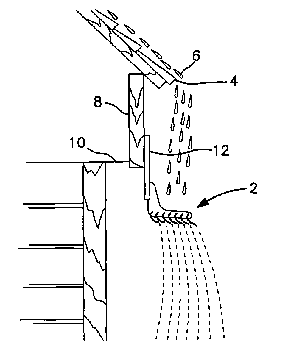
[0022]FIG. 1 of the drawing schematically illustrates the roof water dispersal system in accordance with the present invention in its extended operating position. The dispersal unit, generally designated by reference numeral 2, is mounted beneath the drip edge of a roof, generally designated by reference numeral 4, so that the flow of roof water, generally designated by reference numeral 6, strikes the dispersal unit and is dispersed into smaller droplets or mist which is distributed along a wide area of terrain beneath the roof. The dispersal unit 2 is mounted to the fascia board, designated by reference numeral 8, of a building structure generally designated by reference numeral 10. The dispersal unit 2 is mounted to the fascia board 8 by an adapter unit generally designated by reference numeral 12 which is disposed between the building structure and the dispersal unit. As will be discussed herein, the adapter unit 12 enables the vertical distance between the edge of the roof 4 an...


PUM


Abstract

A roof water dispersal system includes a plurality of longitudinally extending dispersal elements mounted near the edge of a roof structure for receiving and dispersing streams of roof run-off water. The dispersal elements are spaced apart from each other and assembled into a unit to receive streams of roof run-off water, and to disperse the run-off water into droplets or mist to eliminate the erosive effect on the terrain beneath the roof structure which is generally associated with conventional rain gutters. The unit is movable in an upward direction relative to the mounting surface into a retracted storage position, and is vertically movable relative to the roof edge for adjusting the distance between the roof edge and the dispersal elements.

Description

[0001]The present application claims the benefit of U.S. Provisional Patent Application No. 61 / 626,367 filed on Sep. 27, 2011 pursuant to 35 U.S.C. 119(e).BACKGROUND OF THE INVENTION[0002]The present invention is generally directed to roof water dispersal systems such as those generally disclosed in U.S. Pat. No. 3,939,616 entitled “Roof Water Run-Off Dispersal” issued on Feb. 24, 1976 to Richard L. Schapker; U.S. Pat. No. 4,646,488 entitled “Rain Disperser System” issued to Lawrence C. Burns on Mar. 3, 1987; U.S. Pat. No. 5,261,195 entitled “Roof Water Dispersal System” issued on Nov. 16, 1993 to Erwine T. Buckenmaier and Richard J. Urban; U.S. Pat. No. 5,261,196 entitled “Roof Water Dispersal System” issued on Nov. 16, 1993 to Erwine T. Buckenmaier and Richard J. Urban; and U.S. Pat. No. 5,579,611 entitled “Roof Water Dispersal System” issued on Dec. 3, 1996 to Erwine T. Buckenmaier and Richard J. Urban.[0003]The disclosures of the aforementioned 5 United States patents are expres...

Claims


Application Information

Patent Timeline
Patent Type & Authority Patents(United States)
IPC IPC(8): E04D13/00E04D15/00
CPCE04D13/04E04D2013/0463
Inventor BUCKENMAIER, ERWINE T.
Owner BUCKENMAIER ERWINE T
Why Eureka
Try Eureka