
Blank for a rack

a rack and rack technology, applied in the field of racks, can solve the problems of occupying space for exhibition stands, difficult and time-consuming folding, general insufficient collapse resistance and stability, etc., and achieve the effect of quick and easy assembly

Active Publication Date: 2013-09-24
KRISTENSEN TEDDY
View PDF42 Cites 19 Cited by
  • Summary
  • Abstract
  • Description
  • Claims
  • Application Information

AI Technical Summary

Benefits of technology

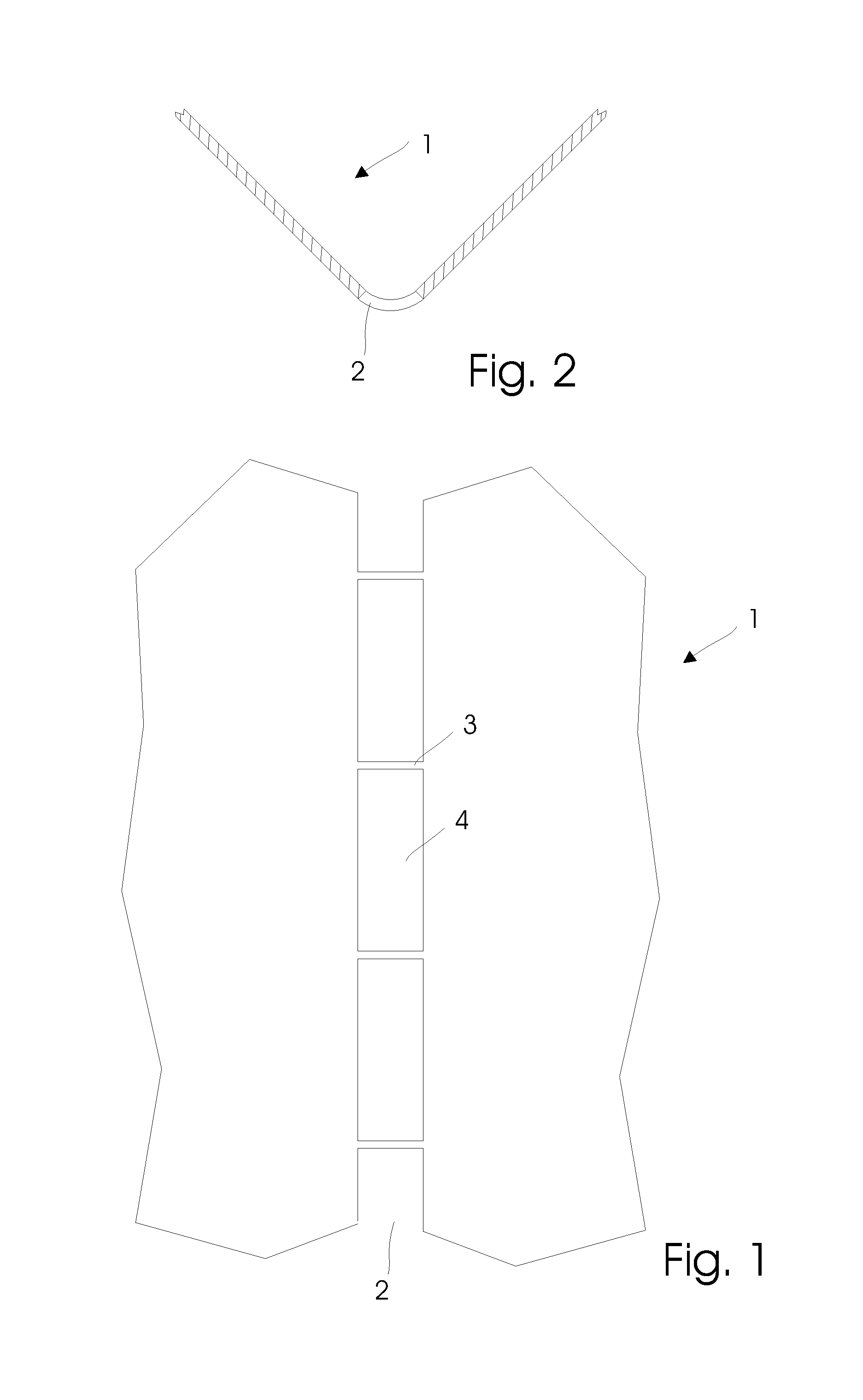
The invention provides a blank that can be easily unfolded into a rack, and a method for making a rack that is cheaper and more durable than previous options. The rack is made by bending different elements of a plate about their bending regions, which allows the rack to carry its weight without needing to be connected further. Using a material that can be formed with permanent deformations, such as metal, makes the rack hard-wearing and long-lasting. The rack can also be extended vertically by adding a new rack with hooks for engaging in the bending regions of the first rack, which creates a secure and stable assembly.

Problems solved by technology

However, exhibition stands take up space, which is usually valuable.
However, these known stands have significant deficiencies in that they are difficult and time consuming to unfold and fold again.
Furthermore, the stands are generally not sufficiently collapse resistant and stable.
Additionally, cardboard is a very weak material, which is not very stable in use.
Thus, an exhibition stand of cardboard will only have a comparatively short lifetime and will in the long run be expensive to use.
In many cases, the flaps are so long that it is not possible to bend them manually about the folding lines unless the plate is thin such as indicated in the patent document.
The known plate is difficult to unfold and assemble into, for example, a sustainable rack.

Method used


Image

  • Blank for a rack
  • Blank for a rack
  • Blank for a rack

Examples


example

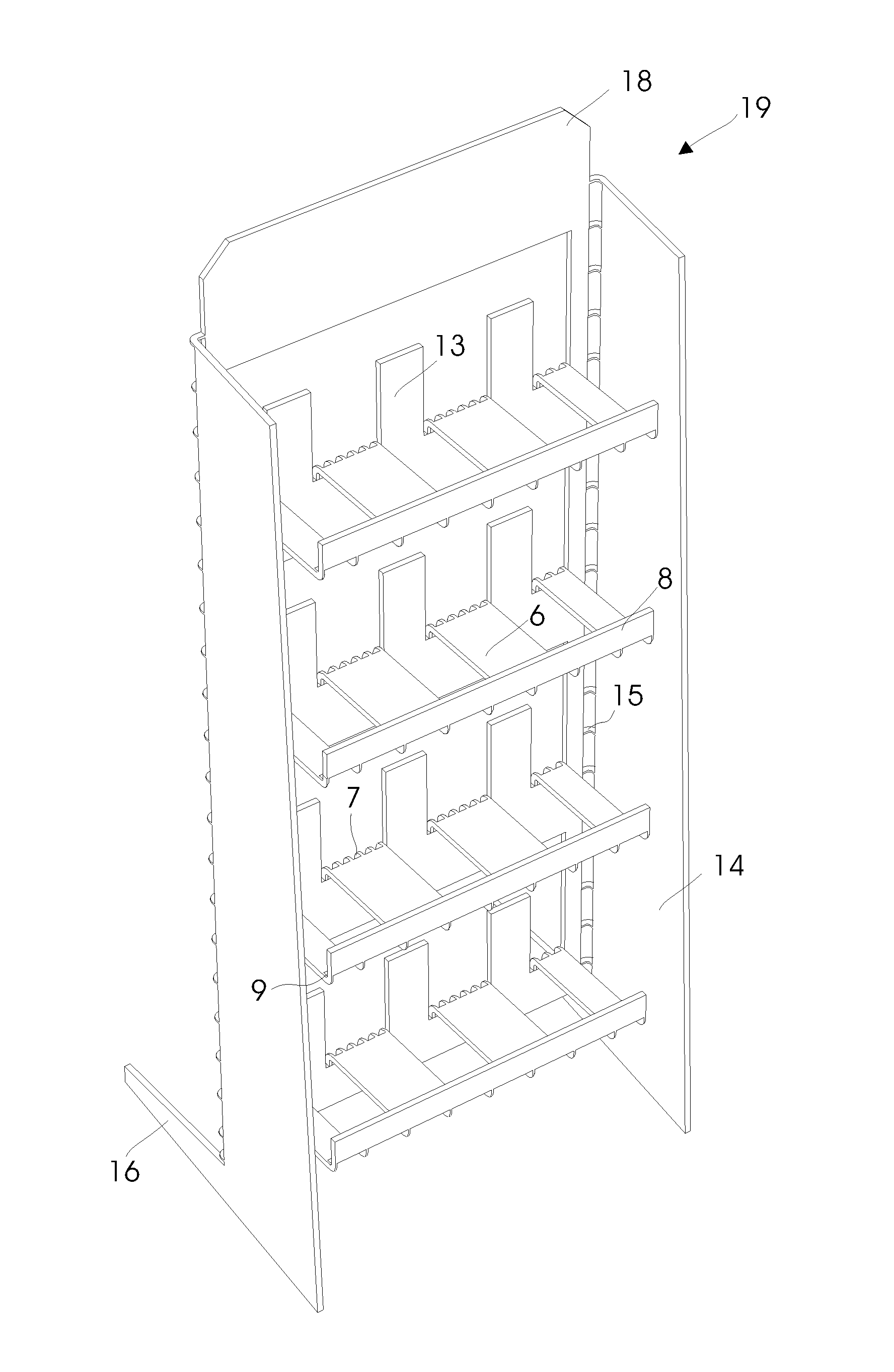
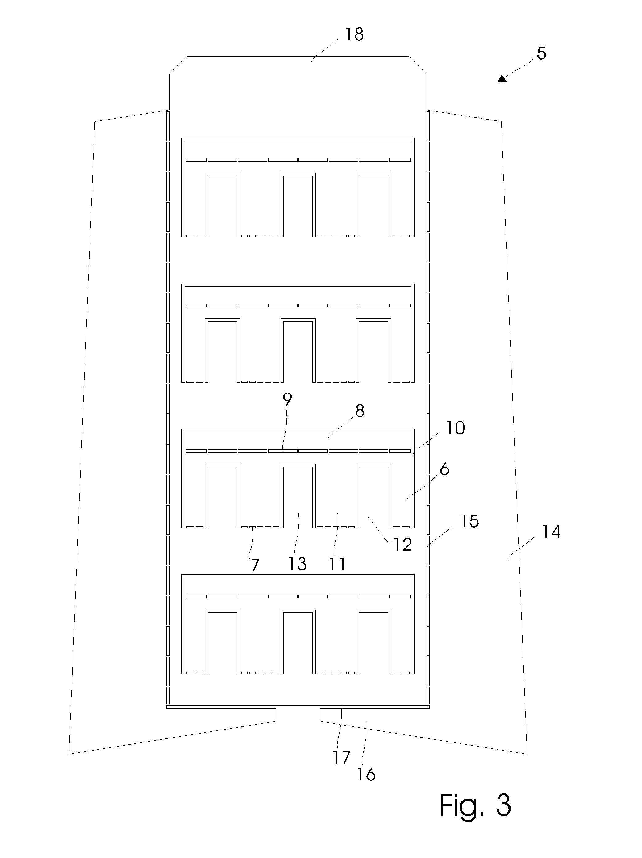
[0091]An exhibition stand of the configuration shown in FIG. 4 was produced by a plate with the pattern shown in FIG. 3. It took approximately 30 seconds. The plate was of ordinary iron and had a thickness of 1.5 mm.

[0092]The bending region of each shelf had the following dimensions:

[0093]

Width of the bending region3mmSpacing between the segments14mmWidth of each segment3mm

[0094]The shelf had a length of 390 mm and a width of 130 mm and was able to carry objects such as e.g. goods with a total weight of approximately 15 kg.

[0095]The shelf was bent about its bending region by pulling in a region at the front edge of the shelf with approximately 10 kg.

[0096]The front edge of each bending region had the following dimensions:

[0097]

Width of the bending region5mmSpacing between the segments52mmWidth of each segment2mm

[0098]The bending region of each side has the following dimensions:

[0099]

Width of the bending region5mmSpacing between the segments52mmWidth of each segment2mm


PUM


Abstract

A blank for a rack with at least one shelf designed as a starting plate with at least one bending region in the form a number of segments and openings. The starting plate includes a number of elements which each have a side extending along a bending region while the other sides of the element are free whereby the rack is quickly and easily formed by bending these elements about their bending regions.

Description

[0001]This application is a 371 filing of International Patent Application PCT / IB2007 / 050793 filed Mar. 9, 2007.BACKGROUND ART[0002]The invention relates to a blank for a rack with at least one shelf, comprising a starting plate of a permanently deformable material that the plate is formed with at least one bending region in the form of a number of segments and openings, that the plate is formed with a number of elements which each have a side that extends along a bending region while at least one of the remaining sides of the elements is free, and that the rack is formed by bending the elements about their bending regions.[0003]Such racks are used to a large extent as exhibition stands for presentation of different objects, e.g. goods in a supermarket. Those companies or shops that use these stands often make use of many and will additionally regularly have a need for quickly and easily to, as a supplement, assemble more than those already in use.[0004]However, exhibition stands ta...

Claims


Application Information

Patent Timeline
IPC IPC(8): A47F5/10
CPCA47F5/10
Inventor KRISTENSEN, TEDDY
Owner KRISTENSEN TEDDY
Learn More