Device for spacing electrical harnesses in a turbomachine

a technology of electrical harnesses and turbomachines, which is applied in the direction of insulated conductors, coupling device connections, cables, etc., can solve the problems of inability to accurately position known devices, limited locations where harnesses can be fastened, and little available space in turbomachines for mounting such harnesses. the effect of simple, effective and inexpensiv

Active Publication Date: 2013-09-24
SN DETUDE & DE CONSTR DE MOTEURS DAVIATION S N E C M A
View PDF11 Cites 19 Cited by
  • Summary
  • Abstract
  • Description
  • Claims
  • Application Information

AI Technical Summary

Benefits of technology

[0007]A particular object of the invention is to provide a solution to these problems that is simple, effective, and inexpensive.
[0009]The strip is thus fastened on the clip support and avoids the spacer device being lost, the distance between the clips being selected so as to avoid any rubbing between the harnesses. The retention means serve to position the spacer device accurately on the corresponding harness and to keep it in the selected position over time.
[0013]The sheath may thus be threaded over an end of the harness and positioned accurately on the harness, after which it may be heated so as to be mechanically bonded on the harness.

Problems solved by technology

Turbomachines present little available space for mounting such harnesses and the locations where the harnesses can be fastened are limited.
Nevertheless, known devices cannot be positioned accurately and they are not mounted on the harnesses in captive manner.

Method used


Image

  • Device for spacing electrical harnesses in a turbomachine
  • Device for spacing electrical harnesses in a turbomachine
  • Device for spacing electrical harnesses in a turbomachine

Examples


first embodiment

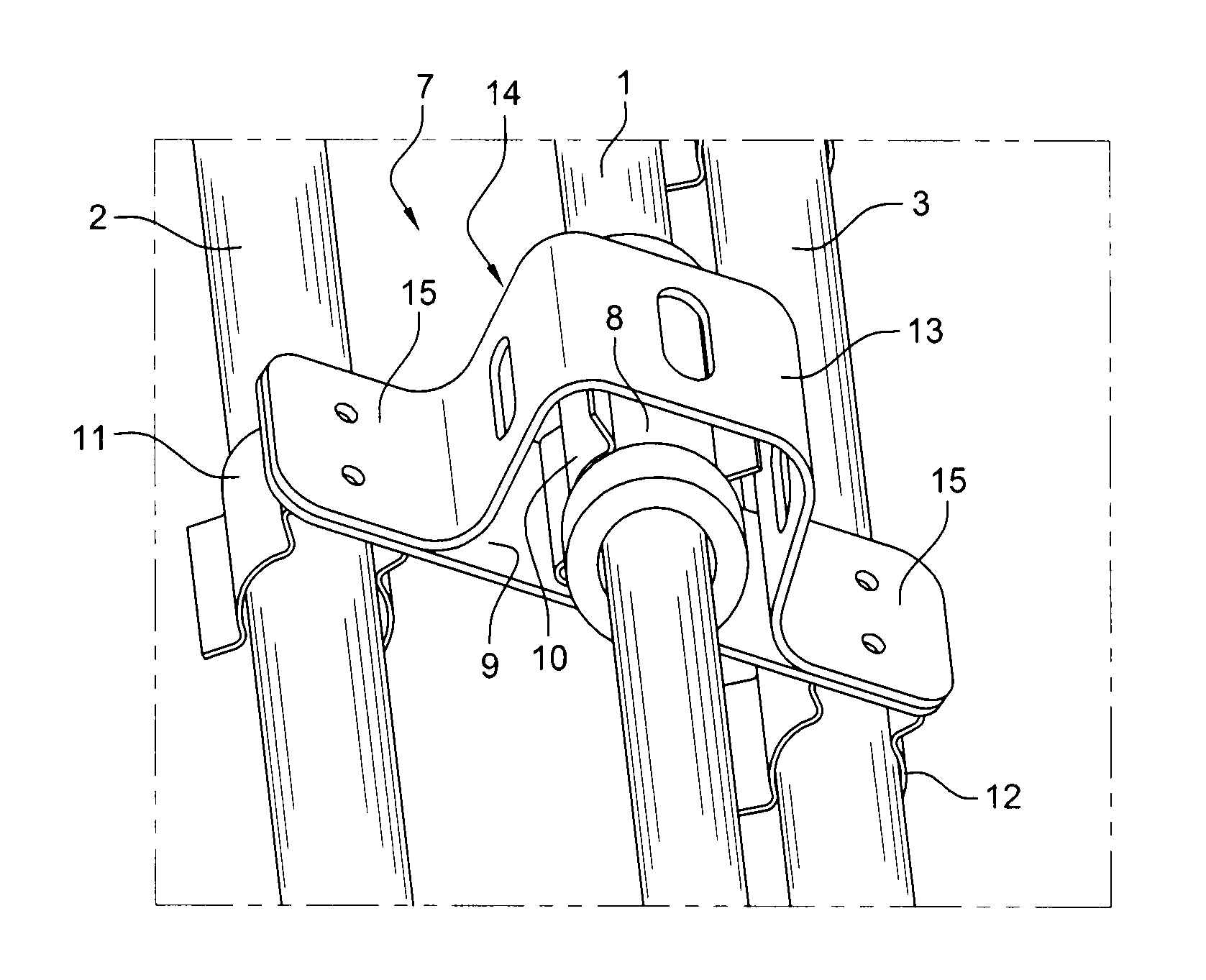
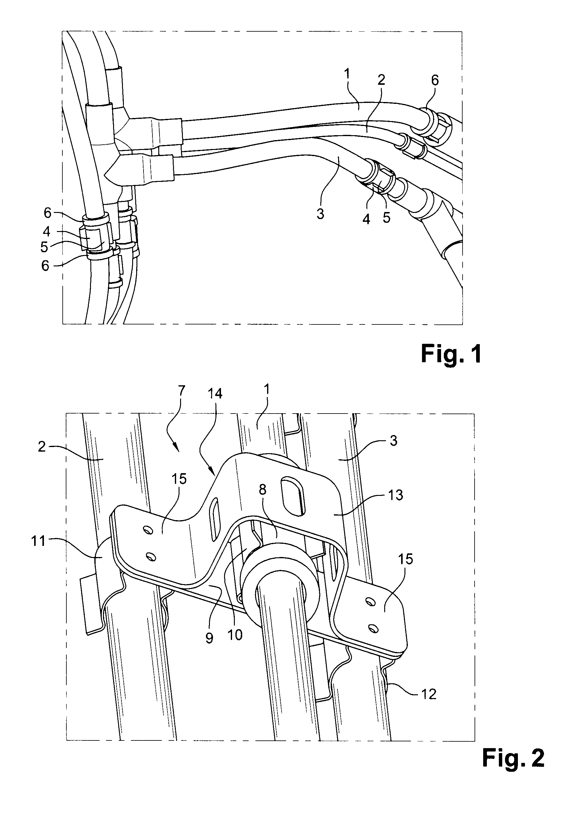
[0031]the spacer device of the invention is shown in FIGS. 2 and 3. This device comprises a plane metal support 9, here formed by a generally rectangular strip, with three clamping spring clips 10, 11, 12 mounted thereon.

[0032]In particular, a first clip 10 is mounted in a middle zone of the support 9 on a first face thereof while the other two clips 11 and 12 are mounted near the ends of the support 9, on its other face. Each clip 10, 11, 12 is in the form of a resilient lyre of structure that is known in particular from document FR 2 906 336.

[0033]The clips 10, 11, 12 are fastened to the support 9 by spot-welding, riveting, or any other known means.

[0034]The spacer device 7 also includes a strip 13 that is mounted on the support 9 around the first clip 10 in order to close it after the harness 1 has been mounted on said clip. The strip 13 has a U-shaped middle portion 14 surrounding the first clip and two tabs 15 projecting from the ends of the U-shape and fastened to the above-me...

second embodiment

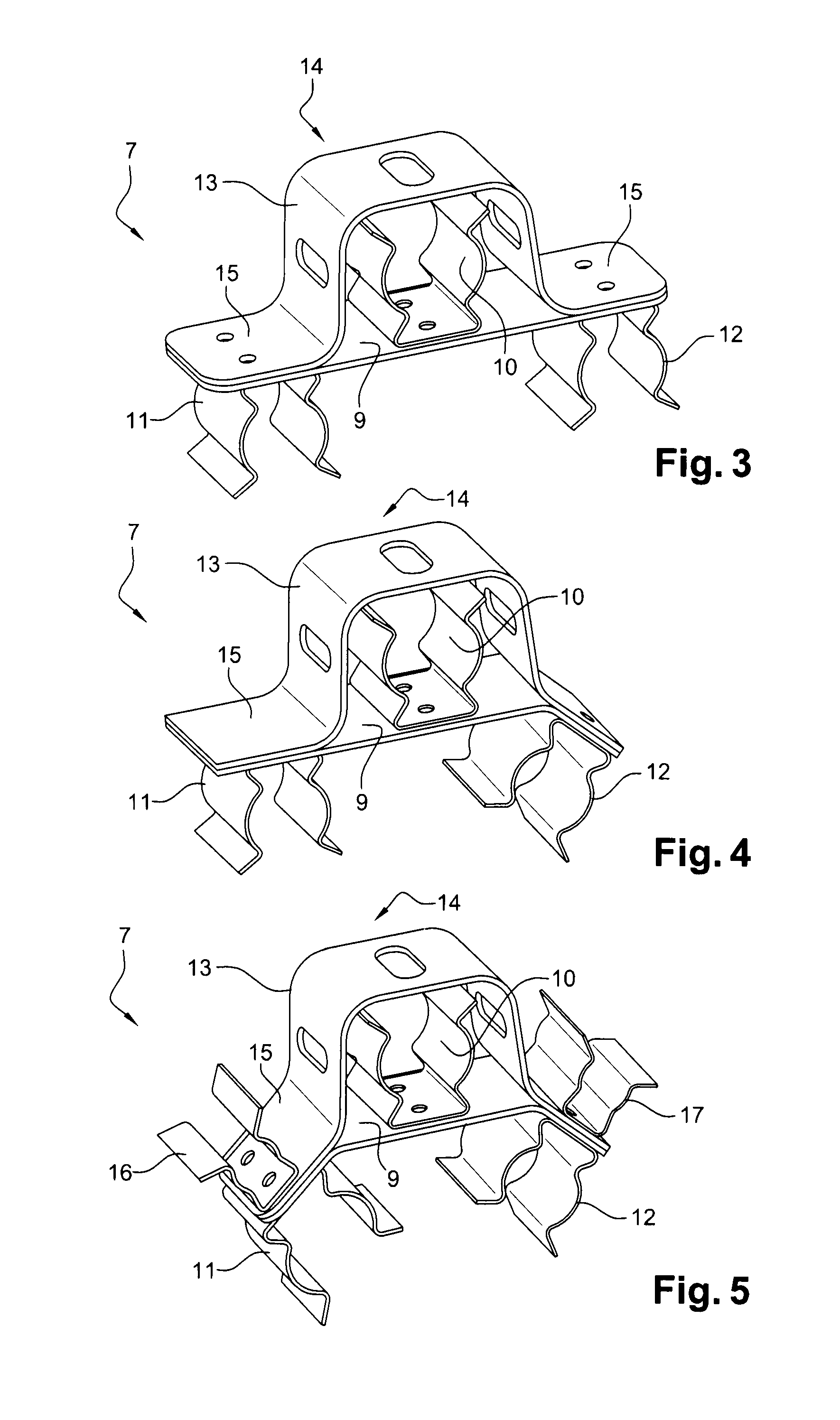
[0037]FIG. 4 shows a second embodiment in which the support 9 has a bent end carrying the clip 12 and forming an angle relative to the middle portion, and to the other end of the support 9 that carries the clips 10 and 11. The shape of the strip 13 is also modified so that its tabs 15 match the ends of the support 9.

[0038]FIG. 5 shows another variant embodiment in which both ends of the support 9 are bent. The shape of the strip 13 is likewise adapted so that the tabs 15 match the bent ends of the support 9.

[0039]In this embodiment, two spring clips 16 and 17, similar to the above-described spring clips 10, 11, 12 but suitable for fastening harnesses of smaller diameters, are fastened on the tabs 15 of the strip 13, on the sides thereof that are opposite from the clips 11 and 12, respectively.

[0040]Naturally, the number of clips and the shape of the support 9 and of the strip 13 could be modified without going beyond the ambit of the invention. Thus, specifically, the spacer device ...


PUM


Abstract

A spacer device for spacing electrical harnesses in a turbomachine such as an airplane turboprop or turbojet is disclosed. The spacer device includes clips fastened on a support. A first clip is mounted on a harness via a retention device which prevents the spacer device from moving relative to the harness, and the spacer device includes a strip mounted around the first clip in order to close the first clip after a harness has been mounted in the first clip. The strip is fastened to the support in a non-releasable manner.

Description

FIELD OF THE INVENTION[0001]The present invention relates to a device for spacing electrical harnesses in a turbomachine such as an airplane turboprop or turbojet.BACKGROUND OF THE INVENTION[0002]The casing of a turbomachine supports various pieces of equipment together with electrical harnesses, i.e. electric cables used for example to power the various pieces of equipment, such as a computer.[0003]The positioning of the harnesses and the paths they follow along the casing are imposed by numerous constraints. Turbomachines present little available space for mounting such harnesses and the locations where the harnesses can be fastened are limited.[0004]Furthermore, it is important to avoid any deterioration of the harnesses, in particular by abrasion due to the harnesses rubbing against one another or against portions of the turbomachine. Such abrasion can occur as a result of the turbomachine vibrating in operation, as a result of relative movements between the turbomachine and the...

Claims


Application Information

Patent Timeline
Patent Type & Authority Patents(United States)
IPC IPC(8): H02G3/04F16L3/08
CPCH02G3/32F01D25/00F02C7/00Y02T50/671F05D2260/30Y02T50/60
Inventor MAZELLE, CHRISTIAN HENRYMARCILLAUD, GUILLAUME
Owner SN DETUDE & DE CONSTR DE MOTEURS DAVIATION S N E C M A
Why Eureka
Try Eureka