
EMI-shielding solutions for computer enclosures using combinations of two and three-dimensional shapes formed in sheet metal

a technology of emishielding solutions and sheet metal, which is applied in the direction of emi leakage reduction, shielding materials, screening casings, etc., can solve the problems that emi will have a difficult time escaping (or entering) the enclosure, and achieve the effect of improving emi shielding, reducing assembly and manufacturing costs, and easy formation of conductive metal

Active Publication Date: 2013-09-24
STEALTHDRIVE
View PDF10 Cites 5 Cited by
  • Summary
  • Abstract
  • Description
  • Claims
  • Application Information

AI Technical Summary

Benefits of technology

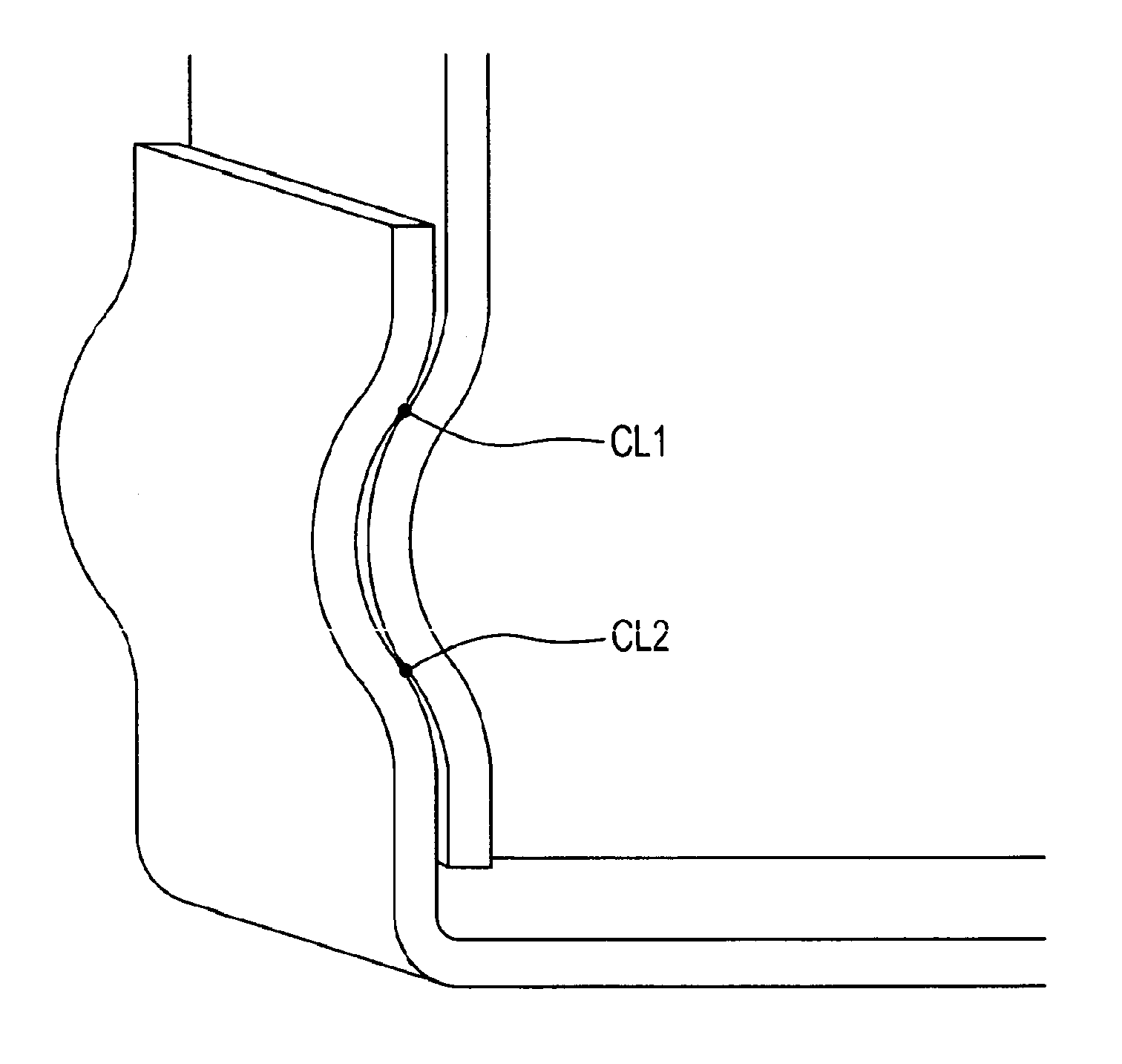
[0062]The present invention removes the need for the single most expensive and least reliable aspect of the electro-mechanical packaging, which is the EMI gasket. The solution(s) provided by the present invention will eliminate the need for gaskets in a great number of applications, as well as “spoons” and other similarly troublesome structures in the PC Chassis and other electronics enclosures. The present invention provides a configuration of placing two and three dimensional shapes into and across the seams of a four-by-two or four-by-one-by-one six sided enclosure, in which the 2D and 3D shapes, which are easily formed in conductive metal (or conductive polymers) allow for improved EMI shielding, but also decrease assembly and manufacturing costs (especially in preferred embodiments). EMI will have a difficult time escaping (or entering) the enclosure because it cannot “see around” the continuous 2D shapes and get trapped and reflected in the 3D attenuating shapes. Particular embodiments use exclusively two or three dimensional shapes, but in a preferred embodiment the 2D and 3D attenuating shapes are combined along the seams as they are needed in both regular and irregular patterns.

Problems solved by technology

EMI will have a difficult time escaping (or entering) the enclosure because it cannot “see around” the continuous 2D shapes and get trapped and reflected in the 3D attenuating shapes.

Method used


Image

  • EMI-shielding solutions for computer enclosures using combinations of two and three-dimensional shapes formed in sheet metal
  • EMI-shielding solutions for computer enclosures using combinations of two and three-dimensional shapes formed in sheet metal
  • EMI-shielding solutions for computer enclosures using combinations of two and three-dimensional shapes formed in sheet metal

Examples


Embodiment Construction

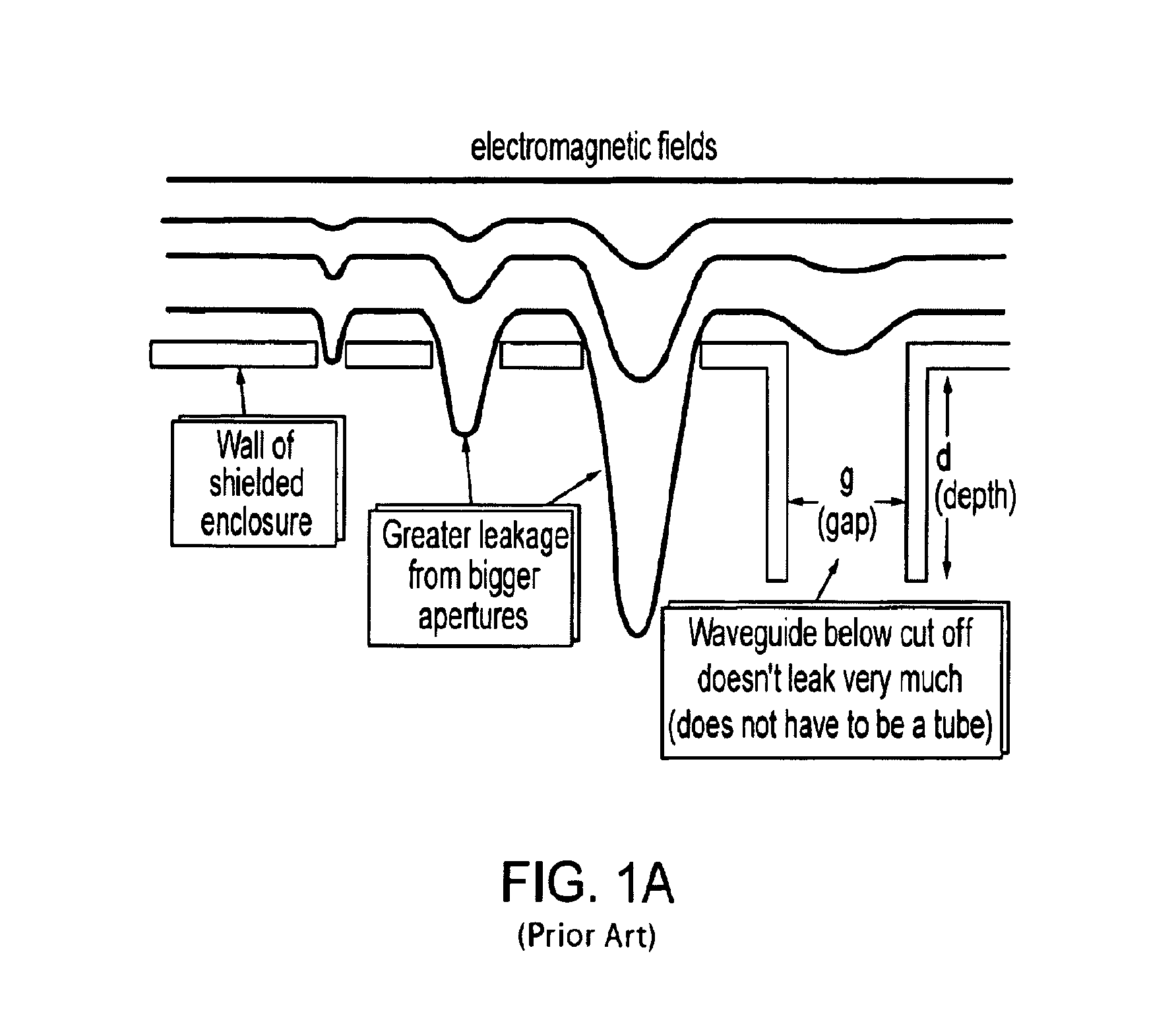
[0090]The half-wave resonance of slot antenna, expressed in the above rule of thumb, is the basis for the solid line in FIG. 1D (and for the rule-of-thumb of FIG. 1E) using the relationship: SE=20 log (λ / 2d). Therefore the degradation associated with a multiple hole pattern is given by: SE reduction=10 log (N), where N=the # of holes in the pattern. Using the relationship: f·λ=c, where is c the speed of light: 3×10^8 m / sec, the frequency in Hz, and λ is the wavelength in meters, where: f=the frequency of the wave λ=the wavelength, c=the speed of light.

[0091]Shielding is the use of conductive materials to reduce EMI by reflection or absorption. Shielding electronic products successfully from EMI is a complex problem with three essential ingredients: a source of interference, a receptor of interference, and a path connecting the source to the receptor. If any of these three ingredients is missing, there is no interference problem. Interference takes many forms such as distortion on a ...


PUM


Abstract

The present invention provides a configuration of a computer-chassis containment or other electromagnetic device method for manufacture in which a “one-hit” solution may be implemented to provide adequate electromagnetic interference shielding (EMC shielding) and is configured such that shielding gaskets, “spoons” or other excessive structures may be reduced or eliminated completely. Patterned sinusoidal “patterns” that are stamped, molded, cut, or extruded into one or more sides of a “box” provide sufficient EMI shielding, such that the need for gaskets is reduced or eliminated.

Description

REFERENCE TO PRIORITY DOCUMENTS[0001]This Application claims priority to under 35 USC 120, and is a continuation in part of U.S. patent application Ser. No. 12 / 071,924, filed Feb. 27, 2008, and is incorporated by reference for all purposes. This application claims priority under 35 USC §119(e) to U.S. Provisional Patent Application Ser. No. 60 / 981,740 entitled EMI Shielding Two and Three Dimensional Configurations in Computer and Electronics Enclosures, filed Oct. 22, 2007, which is incorporated by reference for all purposes.BACKGROUND[0002]The following background section is, in part, reprinted from “Design Techniques for EMC—Part 4 Shielding” by Eur Ing Keith Armstrong, Cherry Clough Consultants, Associate of EMC-UK.[0003]A complete volumetric shield is often known as a “Faraday Cage”, although this can give the impression that a cage full of holes (like Mr Faraday's original) is acceptable, which it generally is not. There is a cost hierarchy to shielding which makes it commercia...

Claims


Application Information

Patent Timeline
Patent Type & Authority Patents(United States)
IPC IPC(8): H01R4/56H05K9/00
CPCH05K9/0009H05K9/0007H05K9/0073H05K9/0049
Inventor COCHRANE, PAUL DOUGLAS
Owner STEALTHDRIVE
Learn More