
Transformable teleoperated amphibious fuel truck

a fuel truck and transceiver technology, applied in the field of amphibious marine vessels, can solve the problems of low fuel drop rate, low fuel supply efficiency, and low fuel supply efficiency of parachutes, and achieve the effect of reducing the cost of fuel supply

Inactive Publication Date: 2013-09-24
THE UNITED STATES OF AMERICA AS REPRESENTED BY THE SECRETARY OF THE NAVY
View PDF33 Cites 3 Cited by
  • Summary
  • Abstract
  • Description
  • Claims
  • Application Information

AI Technical Summary

Benefits of technology

The present invention provides an improved method for transporting liquid supplies between geographically distant locations that are separated in part by water and in part by land. The invention is a marine vessel that can bi-directionally invert and operate in both water and on land. The vessel has a hull with two chambers and two pumping mechanisms, which allows for the controlled inversion of the hull between waterborne conditions. The vessel also includes wheels and a teleoperational system for remote control of speed and direction. The hull can invert from one waterborne condition to the other when the liquid composition between the chambers is shifted in favor of the second chamber or when the vessel is in a land-based condition. The invention provides an efficient and flexible tool for transporting liquid supplies between locations.

Problems solved by technology

LARCs generally are very rugged craft, exceeded their design service life, but are maintenance-intensive.
Although a flexible fuel line arrangement affords a fuel capacity transfer rate that cannot be matched by any reasonable number of fuel-carrying vehicles, it is also vulnerable to enemy action because of its fixed and extensive nature.
Fuel-supply systems involving parachutes have also been known, but parachutes drop very small quantities of fuel.
All of the current fuel-supply systems are manpower-intensive, have limited at-sea range or sea-state capability, and require a separate fuel truck.

Method used


Image

  • Transformable teleoperated amphibious fuel truck
  • Transformable teleoperated amphibious fuel truck
  • Transformable teleoperated amphibious fuel truck

Examples


Embodiment Construction

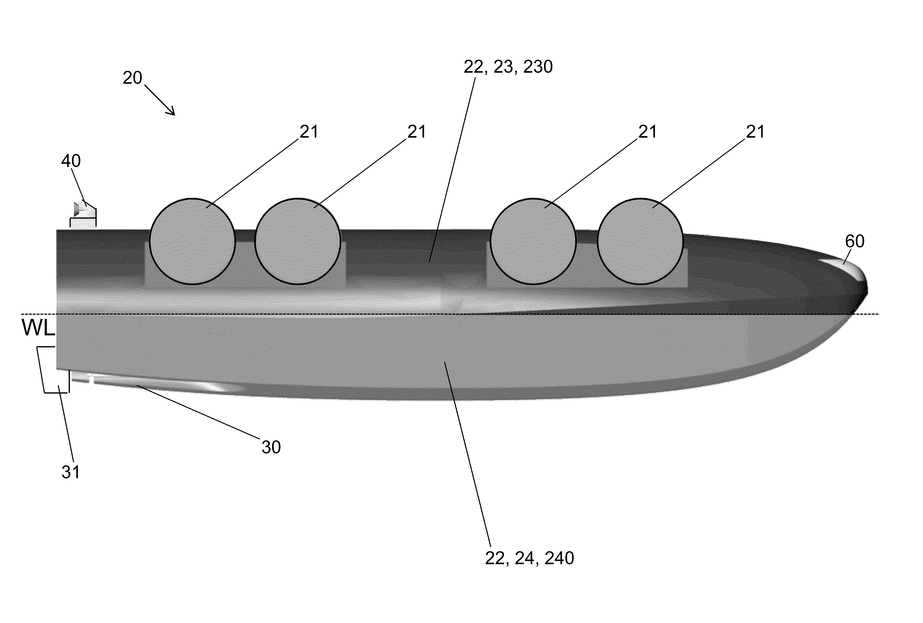
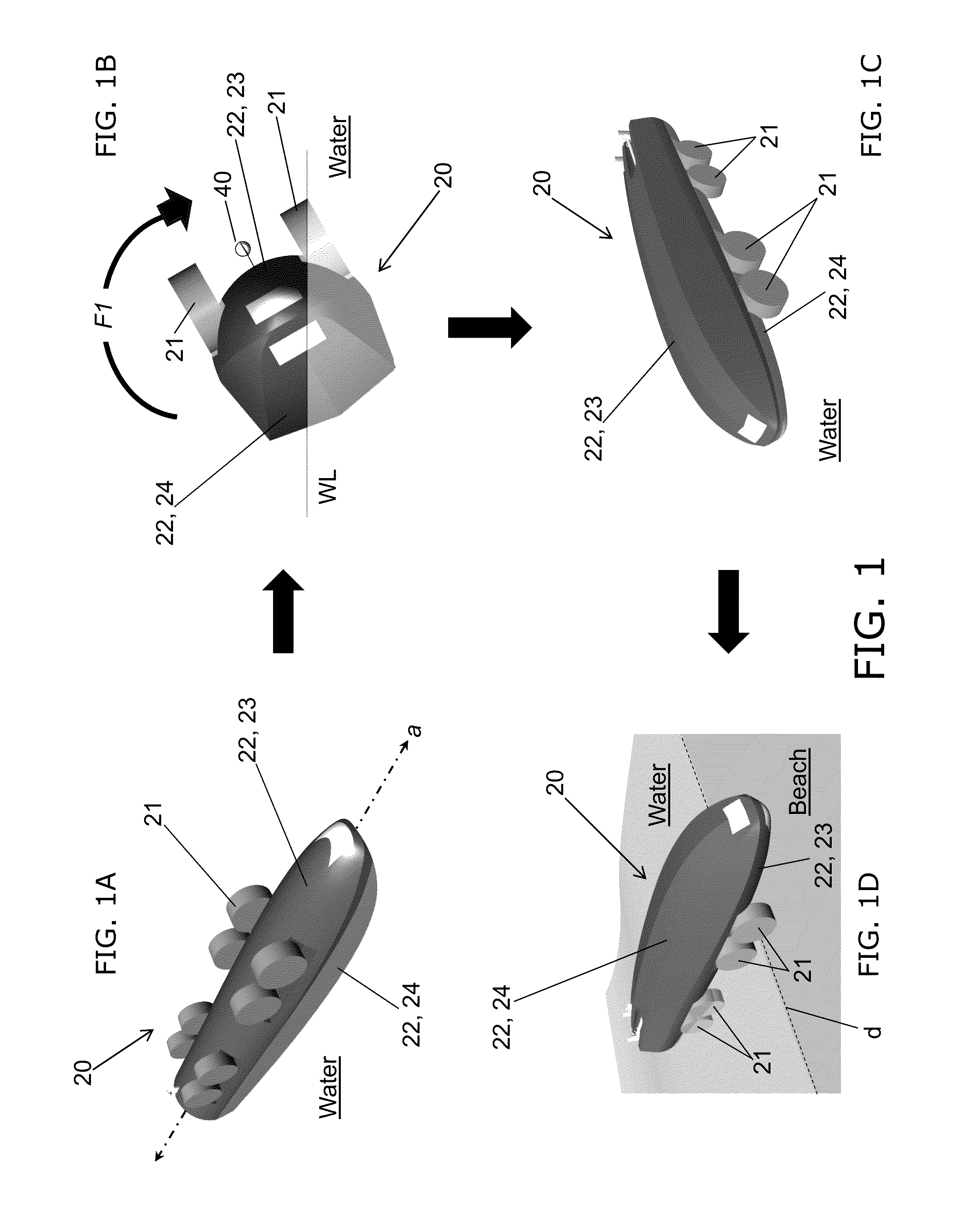
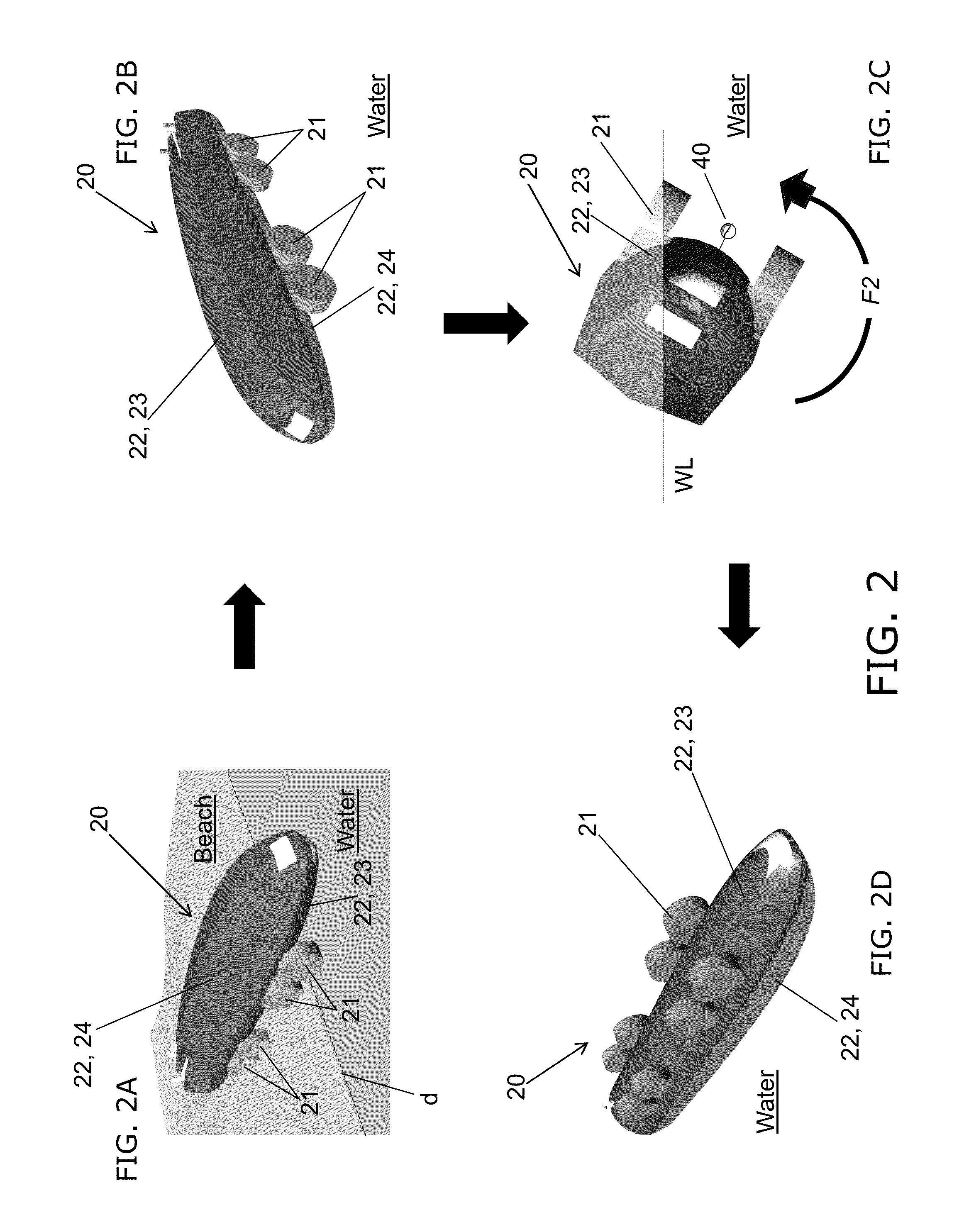
[0027]Referring now to the figures, the present invention's TTAFT vehicle 20 has eight wheels 21 and a hull 22. Wheels 21 are arranged in four coaxial port-and-starboard pairs. Especially as illustrated in FIG. 4 and FIG. 5, inside the hull 22 are a “wheel-side” compartment (e.g., tank) 23 and a “smooth-side” compartment (e.g., tank) 24. Horizontal solid (continuous) bifurcation wall 26 divides (e.g., approximately bisects) hull 22 into two longitudinal hull sections, viz., 230 and 240. Compartments 23 and 24 are separated by horizontal wall 26. Compartment 23 is enclosed by the wheel-side hull section 230. Compartment 24 is enclosed by the smooth-side hull section 240.

[0028]Either or both compartments may have a lining 28 to hold liquid cargo, or to serve as a water ballast tank or bladder for increasing stability of inventive vehicle 20, or for maintaining cargo liquid purity. Ballasting may be particularly useful in smooth-side compartment 24 while the inventive vehicle is in whe...


PUM


Abstract

According to typical practice of the present invention, a vehicle is remotely controlled and is travelable both in water and on land. The vehicle has two liquid-containment components that are situated generally one above the other. Pumping devices bring about transfer of cargo liquid (e.g., fuel or water) from either component to the other component. In accordance with the liquid transfer, the vehicle turns over, about its longitudinal axis, between two generally opposite buoyant positions, each of which is stable and viable for marine navigation. When the flow of the liquid sufficiently shifts weight from one component to the other, the vehicle inverts; that is, the emptying component flips from the bottom to the top, and the filling component flips from the top to the bottom. One of the buoyant positions of the vehicle is characterized by wheels for amphibiously transitioning the vehicle from water travel to land travel.

Description

BACKGROUND OF THE INVENTION[0001]The present invention relates to marine vessels, more particularly to amphibious marine vessels that are suitable for performing auxiliary functions (e.g., transporting personnel and cargo between locations) in military operations or humanitarian relief operations.[0002]For many years the United States Armed Forces have implemented various amphibious vessels for auxiliary purposes such as transporting cargo. For instance, a series of “LARC” (Lighter, Amphibious, Resupply, Craft) vessels has been used, commencing with the introduction in the late 1950's of the LARC 5, an aluminium-hulled wheeled amphibious cargo vehicle capable of transporting five tons. The LARC 5 is sufficiently mobile to traverse sand, coral beaches, unimproved roads, and off-road terrain, and to maneuver through a surf of 10-foot breakers. More recent LARC models have included the LARC 15 (which has a fifteen-ton payload capacity) and the LARC 60 (which has a sixty-ton payload cap...

Claims


Application Information

Patent Timeline
IPC IPC(8): B60F3/00
CPCB60F3/00B60F3/0038B63B2035/008
Inventor KARAFIATH, GABOR
Owner THE UNITED STATES OF AMERICA AS REPRESENTED BY THE SECRETARY OF THE NAVY
Learn More