Reel mower with cutting units suspended by double A arm suspensions

a technology of double a arm suspension and lawnmower, which is applied in the field of lawnmowers, can solve the problems of increasing the tolerance of customers of such equipment, affecting the service life of the mower, and the cutting unit itself being difficult to remove from the rest of the mower, so as to increase the biasing force, and increase the weight of the lawn basket

Active Publication Date: 2013-10-01
TORO CO THE
View PDF26 Cites 8 Cited by
  • Summary
  • Abstract
  • Description
  • Claims
  • Application Information

AI Technical Summary

Benefits of technology

[0010]One more aspect of this invention relates to a reel mower of the general type noted above. In this aspect, the suspension instead of that set forth above simply operatively connects the reel cutting unit to the mower frame. A grass basket is provided for collecting grass clippings cut by the reel cutting unit. The grass basket has a weight that increases with the amount of grass clippings held in the grass basket. The grass basket is operatively connected to a cutting unit frame of the reel cutting unit in a manner that transfers the weight of the grass basket to the reel cutting unit such that the weight of the reel cutting unit is borne by the cutting unit as the cutting unit rolls on the ground. A counterbalance system offsets increasing weight of the grass basket. The counterbalance system comprises at least one biasing member for applying a biasing force to the suspension in a direction that tends to counterbalance the weight of the reel cutting unit including the weight of the grass basket, a sensor for detecting increasing weight of the grass basket due to the grass basket becoming more loaded with grass clippings, and an actuator responsive to the sensor for acting on the biasing member to increase the biasing force to counteract increasing weight of the grass basket.

Problems solved by technology

Thus, to the extent prior art suspensions permitted reel cutting units to cut grass with any unevenness in the cut that could be seen by the visible eye, or the extent prior art grass collectors attached to such reel cutting units permitted grass clippings to fall out or be left on the cut grass path even in minute quantities, the customers of such equipment are becoming increasingly less tolerant of such imperfections.
Access to such a cutting unit is thus difficult.
Moreover, the cutting units themselves can be difficult to remove from the rest of the mower, requiring that they be bolted or unbolted to the mower suspension.

Method used


Image

  • Reel mower with cutting units suspended by double A arm suspensions
  • Reel mower with cutting units suspended by double A arm suspensions
  • Reel mower with cutting units suspended by double A arm suspensions

Examples


Embodiment Construction

The Overall Mower

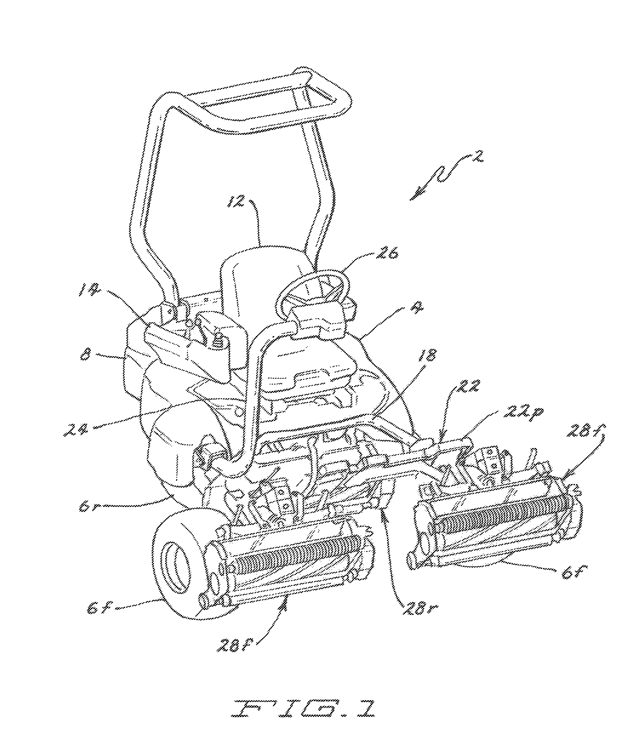
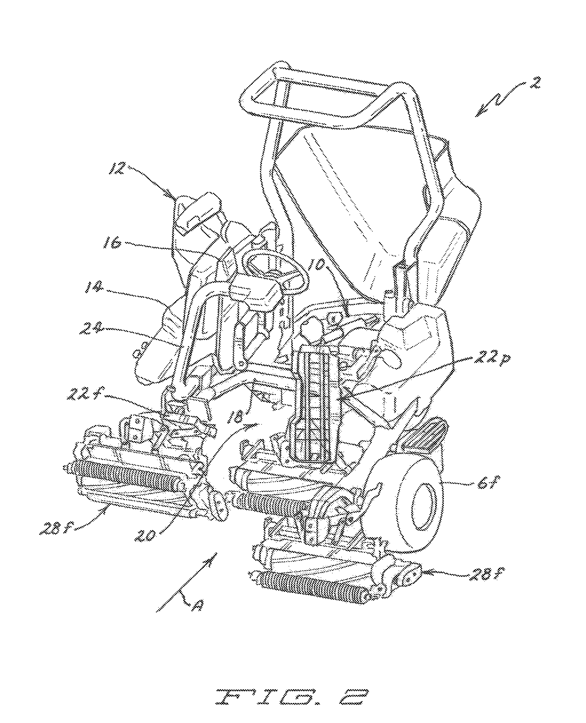
[0040]FIGS. 1 and 2 illustrate one embodiment of a mower 2 according to this invention. Mower 2 comprises a frame 4 supported for rolling over the ground by a pair of front wheels 6f and a single rear wheel 6r arranged in a triangular configuration. The rear of mower frame 4 includes an engine compartment 10 that is normally covered and enclosed by an engine shroud or hood 8. An internal combustion engine or other suitable power source, such as a battery pack, hybrid electric drive system, fuel cell, etc., is mounted in engine compartment 10. Various other components can be housed on or adjacent the engine within engine compartment 10, such as drive train components, controls, etc.

[0041]A hydraulic system (not shown) is carried on mower frame 4 and is powered by the engine for providing pressurized hydraulic fluid flow for powering various components of mower 2. For example, the hydraulic system includes an engine driven hydraulic pump that powers one or more hydrau...


PUM


Abstract

A reel mower has a plurality of reel cutting units. Each reel cutting unit is connected to a frame of the reel mower by its own double A arm suspension that lowers a reel cutting unit into a cutting position in a tail down orientation and that levels the reel cutting unit out as it lifts the reel cutting unit into a transport position.

Description

CROSS REFERENCE TO RELATED APPLICATIONS[0001]This application claims the benefit of previously filed provisional application Ser. No. 61 / 133,285, filed Jun. 27, 2008.TECHNICAL FIELD[0002]This invention relates to a reel mower having one or more reel cutting units that each comprises a rotatable cutting reel that sweeps grass against a sharpened bedknife for shearing the grass against the bedknife.BACKGROUND OF THE INVENTION[0003]Reel mowers having a self propelled mower frame and mounting a plurality of reel cutting units are well known for precision mowing of grass. In such mowers, the reel cutting units typically are self-supporting and roll over the ground during cutting using one or more ground engaging rollers carried on the reel cutting unit itself. A suspension mounts each such reel cutting unit to the mower frame so that the reel cutting units are propelled by motion of the mower frame. The suspension is designed to allow the reel cutting unit various degrees of freedom of m...

Claims


Application Information

Patent Timeline
Patent Type & Authority Patents(United States)
IPC IPC(8): A01D34/53
CPCA01D34/44A01D43/063A01D34/54A01D34/43A01D75/306A01D34/62A01D2101/00
Inventor GOMAN, GERALD E.GALEWSKI, RICKY A.LAMUSGA, GARY R.
Owner TORO CO THE
Why Eureka
Try Eureka