Device for testing thin specimens in pure bending

a thin specimen and pure bending technology, applied in measurement devices, instruments, scientific instruments, etc., can solve the problems of failure to characterize the nonlinear constitutive behavior over the full strain range common to deployable structures, subject to strain levels and deformations outside of traditional composite structural applications, and difficult design and analysis of deployable structures

Inactive Publication Date: 2013-10-01
THE UNITED STATES OF AMERICA AS REPRESETNED BY THE SEC OF THE AIR FORCE
View PDF4 Cites 38 Cited by
  • Summary
  • Abstract
  • Description
  • Claims
  • Application Information

AI Technical Summary

Benefits of technology

[0007]The device is designed for testing under pure bending conditions thin composite laminate specimens used as flexural elements in deployable structures used in space applications. While the use of composite laminates in deployable structures has become widely acceptable, they are subjected to large deformations with strain levels well beyond what classical theories predict. This test device was designed to be used in an ordinary test frame. The test specimen is clamped between two carts with rotating bearings located on two parallel tracks allowing horizontal movement. Each cart has a near vertical arm with a third rotating bearing at the upper end. Cross members apply force to the vertical arms causing the carts to move and stressing the specimen into an arc of up to 180 degrees.

Problems solved by technology

While the use of composite laminates in deployable structures is widely acceptable, in operation they are subjected to strain levels and deformations outside of traditional composite structural applications.
As such, their behavior is poorly understood, making deployable structure design and analysis extremely difficult.
Data from these tests yield accurate, basic properties that are useful for laminate design, but they fail to characterize the nonlinear constitutive behavior over the full strain range common to deployable structures.
Attempts at analytically quantifying these increased strengths have largely been ineffective or are not applicable to the thin laminates used in deployable structures.
Furthermore, the extrapolation of classical bending theory, which assumes linear-elastic behavior, is of little value due to nonlinear composite stiffening and softening with increasing and decreasing strains respectively.
Finally, the matter is further complicated by laminate thickness concerns for composites in bending.
This test method does not generate a pure stress state in the specimen and does not allow a direct measurement of curvature, bending moment, or strain.
While the use of composite laminates in deployable structures has become widely acceptable, they are subjected to large deformations with strain levels well beyond what classical theories predict.

Method used


Image

  • Device for testing thin specimens in pure bending
  • Device for testing thin specimens in pure bending
  • Device for testing thin specimens in pure bending

Examples


Embodiment Construction

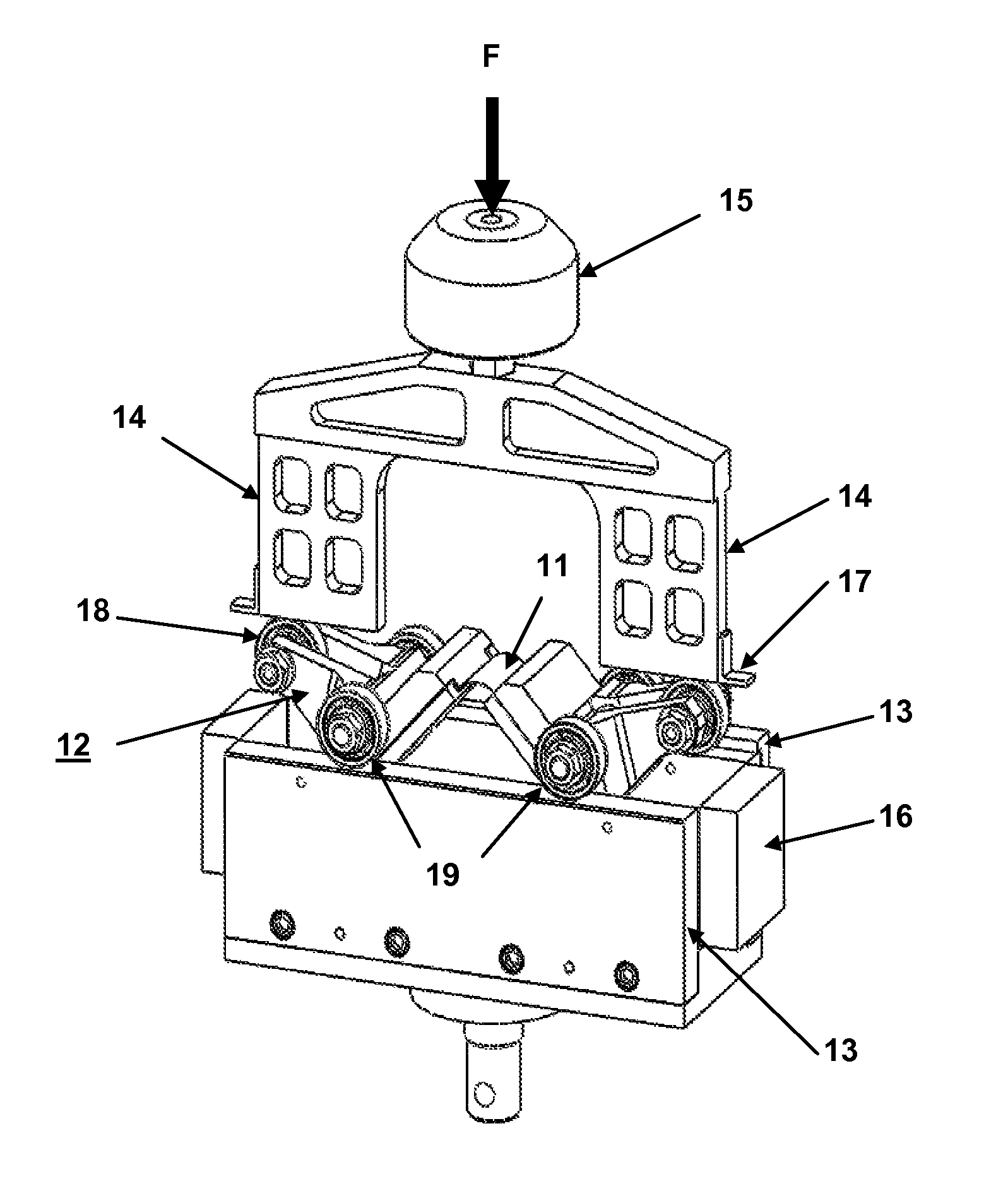
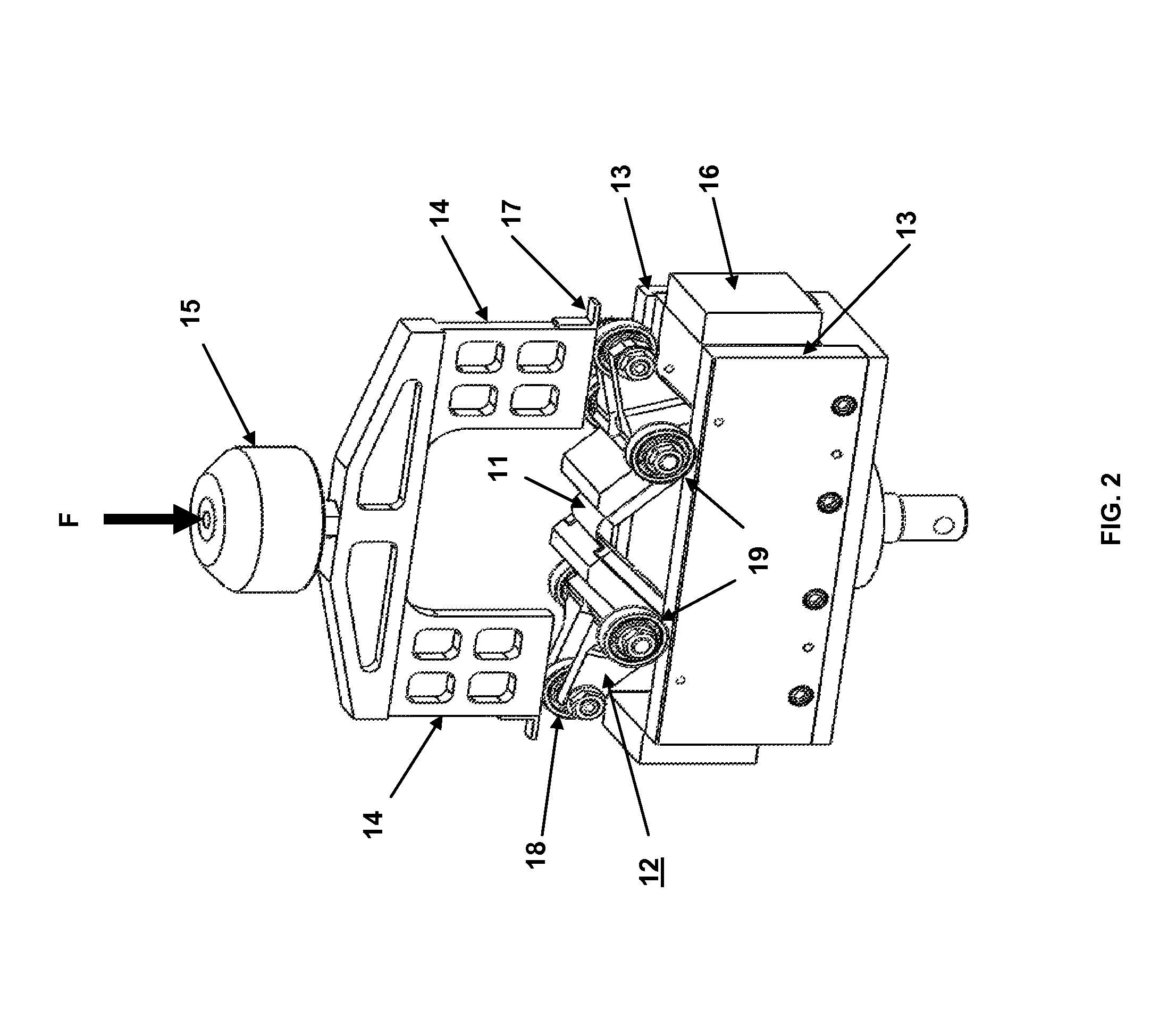
[0018]An improved test fixture has been designed that allows pure moment to be imparted into the composite test coupon (thin composite laminate specimen). As shown in FIG. 2, the test fixture is used to clamp a coupon 11 between two rotating carts 12 that are driven downward by the cross members 14 pushing downward upon the bearings 18 at the end of the near vertical arms of the carts. As the cross members 14 move downward, the carts rotate about the axes of the lower bearings 19, thus apply the bending moment on the coupon 11. The carts are very stiff compared with the coupon and are considered perfectly rigid. As the coupon deforms, the carts translate along tracks 13 until they reach the extreme position that corresponds to a coupon arc angle of 180° or until the coupon fails. Load (F) and cross member displacement are measured to calculate the applied moment and curvature. The load cell 15 placed between the cross member and the test frame is used to measure the applied load F. ...


PUM

PropertyMeasurementUnit
arc angleaaaaaaaaaa
bending propertiesaaaaaaaaaa
lengthaaaaaaaaaa

Abstract

An improved test fixture to evaluate thin composite laminates commonly used in deployable space structures. The fixture is designed to impart a pure moment into the coupon, a necessary improvement to prior test methods where results are obtained by fitting material properties in a nonlinear structural analysis of the test. Fixture mechanics allow for direct calculation of the coupon flexural modulus and allowable flexural strain based on two key measurements, fixture displacement and applied load.

Description

STATEMENT OF GOVERNMENT INTEREST[0001]The conditions under which this invention was made are such as to entitle the Government of the United States under paragraph 1(a) of Executive Order 10096, as represented by the Secretary of the Air Force, to the entire right, title and interest therein, including foreign rights.BACKGROUND OF THE INVENTION[0002]The invention relates generally to testing of flexure specimens to determine strain and elastic modulus, and in particular to a device designed to allow testing under pure bending conditions of thin composite laminates used as flexural elements.[0003]Thin composite laminates are commonly used in deployable space structures. In application, the laminates are elastically folded to allow a structure to be compactly stowed during launch and subsequently deployed to an operational state once in orbit. This basic technology enables operational systems containing structures such as solar arrays, reflectors, antennas, and booms to be efficiently...

Claims


Application Information

Patent Timeline
Patent Type & Authority Patents(United States)
IPC IPC(8): G01N3/20
CPCG01N3/20G01N2203/0096G01N2203/0282G01N2203/0435
Inventor ARDELEAN, EMIL V.MURPHEY, THOMAS W.SANFORD, GREGORY E.
Owner THE UNITED STATES OF AMERICA AS REPRESETNED BY THE SEC OF THE AIR FORCE
Why Eureka
Try Eureka