Method for Forming Reinfoced Pultruded Profiles

Inactive Publication Date: 2013-06-13
TICONA LLC
View PDF6 Cites 46 Cited by
  • Summary
  • Abstract
  • Description
  • Claims
  • Application Information

AI Technical Summary

Benefits of technology

[0005]In accordance with another embodiment of the present invention, a pultrusion apparatus for forming a profile is disclosed. The apparatus comprises a pultrusion die that defines an interior cavity, a pulling device that is configured to pull one or more continuous fiber ribbons through the interior cavity of the pultrusion die, a cross-head extrusion device that is configured to extrude a disco

Problems solved by technology

The transverse strength properties of such profiles however, are often poor, which can cause the material to split when a stress is applied in a cross-machine direction (transverse).
One problem with this method, however, it is that it relies upon a thermoset resin to help achieve the desired strength properties.
Suc

Method used


Image

  • Method for Forming Reinfoced Pultruded Profiles
  • Method for Forming Reinfoced Pultruded Profiles
  • Method for Forming Reinfoced Pultruded Profiles

Examples


example

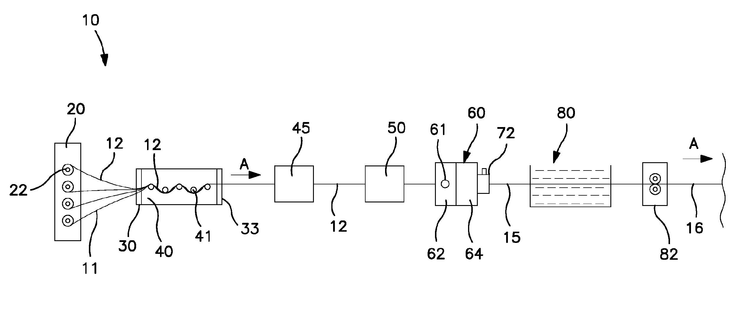
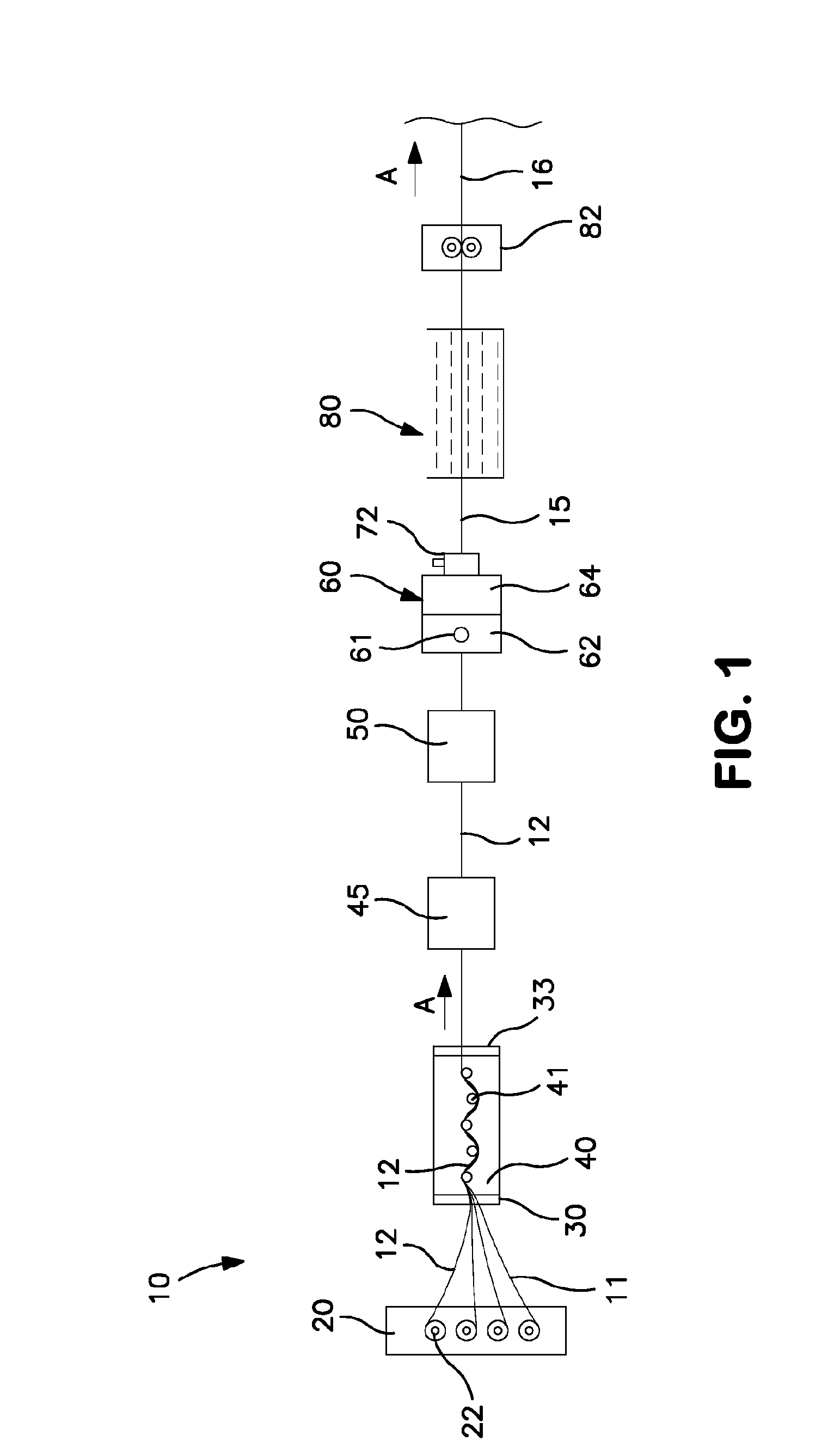
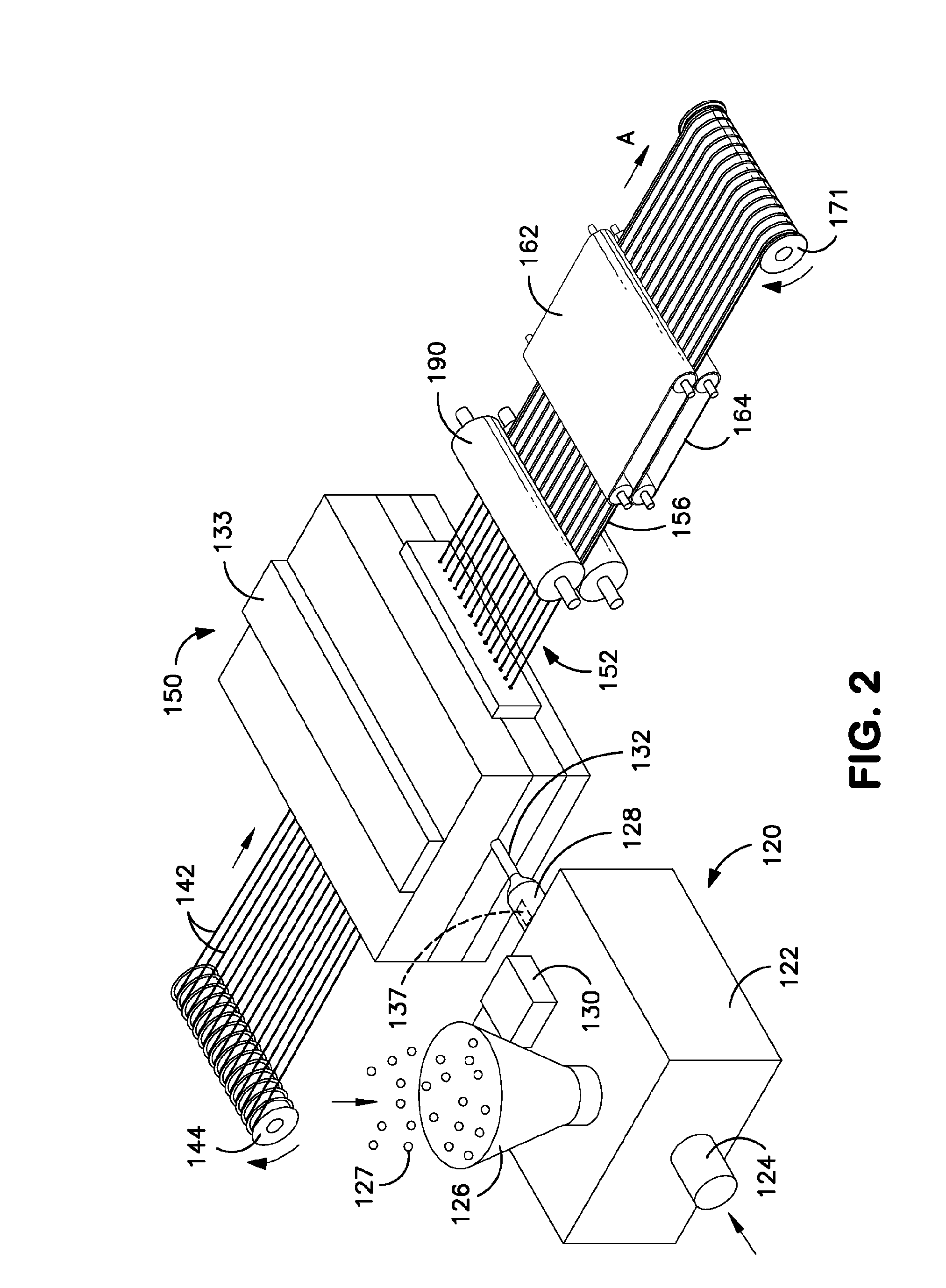
[0097]Continuous fiber ribbons were initially formed using an extrusion system as substantially described above and shown in FIGS. 2-3. Glass fiber rovings (E-glass, 2200 tex) were employed for the continuous fibers with each individual ribbon containing three (3) fiber rovings. The thermoplastic polymer used to impregnate the fibers was acrylonitrile butadiene styrene (ABS), which has a melting point of about 105° C. Each ribbon contained 60 wt. % glass fibers and 40 wt. % ABS. The resulting ribbons had a thickness of between 0.2 to 0.4 millimeters and a void fraction of less than 1%.

[0098]Once formed, the ribbons were then fed to an extrusion / pultrusion line operating at a speed of 5 feet per minute. Prior to consolidation, the ribbons were heated within an infrared oven (power setting of 160). The heated ribbons were then supplied to a consolidation die having a U-shaped channel that received the ribbons and consolidated them together while forming the initial shape of the profil...


PUM

PropertyMeasurementUnit
Fractionaaaaaaaaaa
Thicknessaaaaaaaaaa
Thicknessaaaaaaaaaa

Abstract

A method and apparatus for forming a profile that contains at least one layer of continuous fibers and at least one layer of discontinuous fibers. Said method allowing the selective control of features to achieve a profile that has increased transverse strength and flexural modulus. The layer of continuous fibers may be formed from one or more continuous fiber reinforced ribbons (“CFRT”) (12) that contain fibers embedded within a thermoplastic polymer matrix, whereby a void fraction and in turn is minimized and flexural modulus is optimized Further, the ribbon (s) are consolidated so that the continuous fibers remain fixed in alignment in a substantially longitudinal direction (e.g., the direction of pultrusion). In addition to enhancing the tensile properties of the profile, the use of such ribbons also allows an improved handability when placing them into the desired position within the pultrusion die. The discontinuous fibers are also embedded within a thermoplastic matrix, in such a way as to assist in bonding of the layers to achieve the desired strength. At least a portion of the fibers are oriented in the transverse direction to provide increased transverse strength.

Description

RELATED APPLICATIONS[0001]The present application claims priority to Provisional Application Ser. No. 61 / 357,289, filed on Jun. 22, 2010, the entire contents of which are incorporated herein by reference thereto.BACKGROUND OF THE INVENTION[0002]Fiber reinforced profiles are often formed by pulling (“pultruding”) continuous fibers through a resin and then shaping the fiber-reinforced resin within a pultrusion die. Because the profiles have continuous fibers oriented in the machine direction (longitudinal), they often exhibit a high tensile strength in the machine direction. The transverse strength properties of such profiles however, are often poor, which can cause the material to split when a stress is applied in a cross-machine direction (transverse). In this regard, various attempts have been made to strengthen profiles in the transverse direction. For example, U.S. Pat. No. 7,514,135 to Davies, et al. describes a pultruded part formed by providing a first layer of reinforcing rov...

Claims


Application Information

Patent Timeline
IPC IPC(8): B29C70/08
CPCB29B15/122B29C70/081B29C70/08B29C70/521B29C70/525B29C70/52Y10T428/249921
Inventor NELSON, SHERRI M.EASTEP, DAVID W.REGAN, TIMOTHY A.
Owner TICONA LLC
Why Eureka
Try Eureka