Self-illuminating battery

a self-illuminating, battery technology, applied in the field of electromechanical technology, can solve the problems of battery capacity decline, customer inability to watch the remaining capacity in a dark environment, production craft of batteries is different, and cannot contain the same power, etc., to achieve the effect of low cost, long use life and large convenien

Active Publication Date: 2013-10-01
GUANGZHOU TIGER HEAD BATTERY GROUP
View PDF18 Cites 1 Cited by
  • Summary
  • Abstract
  • Description
  • Claims
  • Application Information

AI Technical Summary

Benefits of technology

[0009]There are several advantages of this invention. First, because the thin-film light-emitting diode is fixed on the outer surface of the battery, we don't need to modify a lot in the existing battery product line. Therefore, we can achieve a new function in the lowest cost. Second, the battery is equipped with a luminescence light-emitting diode, so it illuminates without the need of a flash fight. It can provide a large convenience when suffering earthquake or other emergency situations. Third, the battery has a long using life due to the high energy conversion efficiency. Besides, setting an elastic membrane switch in the light-emitting diode can control the illuminating time of light-emitting diode. Furthermore, this invention can show the remaining capacity of the battery, which is convenient to make full use of the battery and is good for environmental protection.
[0010]This invention makes an improvement of batteries, and the new adding function will not affect the power supply functions which battery using in other electric apparatus. This is an important difference between the new invention and existing light-emitting diode technology.

Problems solved by technology

The remaining capacity can be shown by liquid crystal; however, liquid crystal does not have an illumination function, so customers cannot watch the remaining capacity in a dark environment.
The disadvantage of this patent is that it will cause the battery capacity to decrease if we don't change the battery's size, because incorporating the light-emitting diode and the battery will cause the light-emitting diode to occupy the inner space of the battery.
The production craft of the battery is different and cannot contain the same power as before.

Method used


Image

  • Self-illuminating battery
  • Self-illuminating battery

Examples


example 1

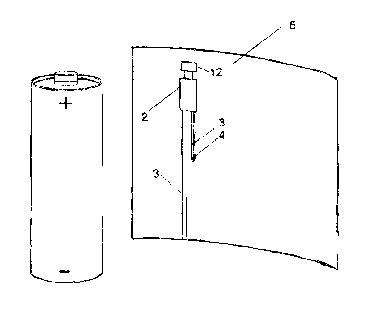
Implemental see also FIG. 1

[0014]This invention sets up a thin-film light-emitting diode 12 on an outer surface of a battery, the thin-film light-emitting diode 12 links with the battery's positive and negative poles through a conductor 3, the light-emitting diode is powered by the battery; there is an elastic membrane switch set in the power supply circuit of the light-emitting diode. The elastic membrane switch is consisted of a lead 3 and an insulator 4 that has small holes. It is normally off. The lead 3 links with the battery's negative pole through the small holes when giving outside force, and the light-emitting diode will illuminate; the light-emitting diode is disposed between the packaging wrap 5 and the main battery body.

example 2

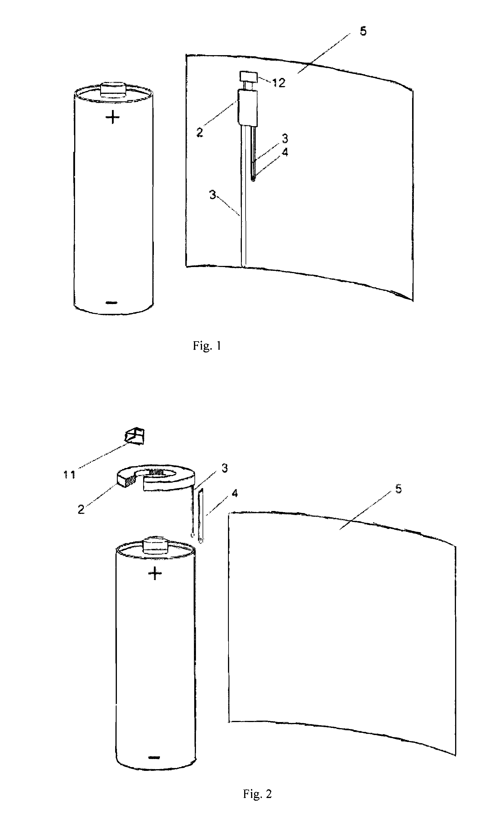
Implemental see also FIG. 2

[0015]Light-emitting diode is fixed on a top or bottom end of a battery. The top end of the battery is a positive pole, the bottom end of the battery is a negative pole, so the light direction of light-emitting diode generally tracks the longitudinal axis of the battery for convenience.

[0016]With reference to FIGS. 1 and 2, the self-illuminating battery may include a driving circuit 2, a conductor 3, a membrane switch insulator 4, a packaging wrap 5 and a micro light emitting diode 11 or a thin-film light emitting diode 12.

[0017]Considering some light-emitting diode's illuminating voltage are higher than 1.5V, however, the common family battery, namely, D, C, AA, AAA, their voltages are around 1.5V. To be an improvement, a driving circuit is set at a top of the battery, and linking with the light-emitting diode, using to complete voltage conversion between the common family batteries' 1.5V and the light-emitting diode's voltage.


PUM


Abstract

A self-illuminating battery including one or more film light-emitting diodes positioned adjacent an inner surface of a battery casing. The diodes are connect to positive and negative poles through conductor. The battery may also include one or more miniature light-emitting diode mounted at the end of the battery, connecting the positive pole and negative pole through conductor.

Description

FIELD OF TECHNOLOGY[0001]This invention concerns electronic technology.TECHNOLOGY BACKGROUND[0002]The batteries which can show their remaining capacity in today's market, such as Duracell®, they have a liquid crystal linking positive and negative poles, which is between the surface of battery and its packaging wrap. The remaining capacity can be shown by liquid crystal; however, liquid crystal does not have an illumination function, so customers cannot watch the remaining capacity in a dark environment. China patent 200720032012 discloses a battery that provides not only a power supply but also illumination. There is a light-emitting diode linking the battery's positive pole and negative pole. And a light-emitting diode is incorporated with the battery. The disadvantage of this patent is that it will cause the battery capacity to decrease if we don't change the battery's size, because incorporating the light-emitting diode and the battery will cause the light-emitting diode to occup...

Claims


Application Information

Patent Timeline
Patent Type & Authority Patents(United States)
IPC IPC(8): F21L4/00
CPCH01M6/5044H01M10/488Y02E60/10F21L4/005
Inventor LU, YI
Owner GUANGZHOU TIGER HEAD BATTERY GROUP
Why Eureka
Try Eureka