
Inductive toy vehicle

a toy vehicle and inductive technology, applied in the direction of toys, remote-control toys, model railways, etc., can solve the problems of reducing the conductivity, and affecting the operation of the vehicl

Active Publication Date: 2013-10-01
PHILIPS IP VENTURES BV
View PDF54 Cites 21 Cited by
  • Summary
  • Abstract
  • Description
  • Claims
  • Application Information

AI Technical Summary

Benefits of technology

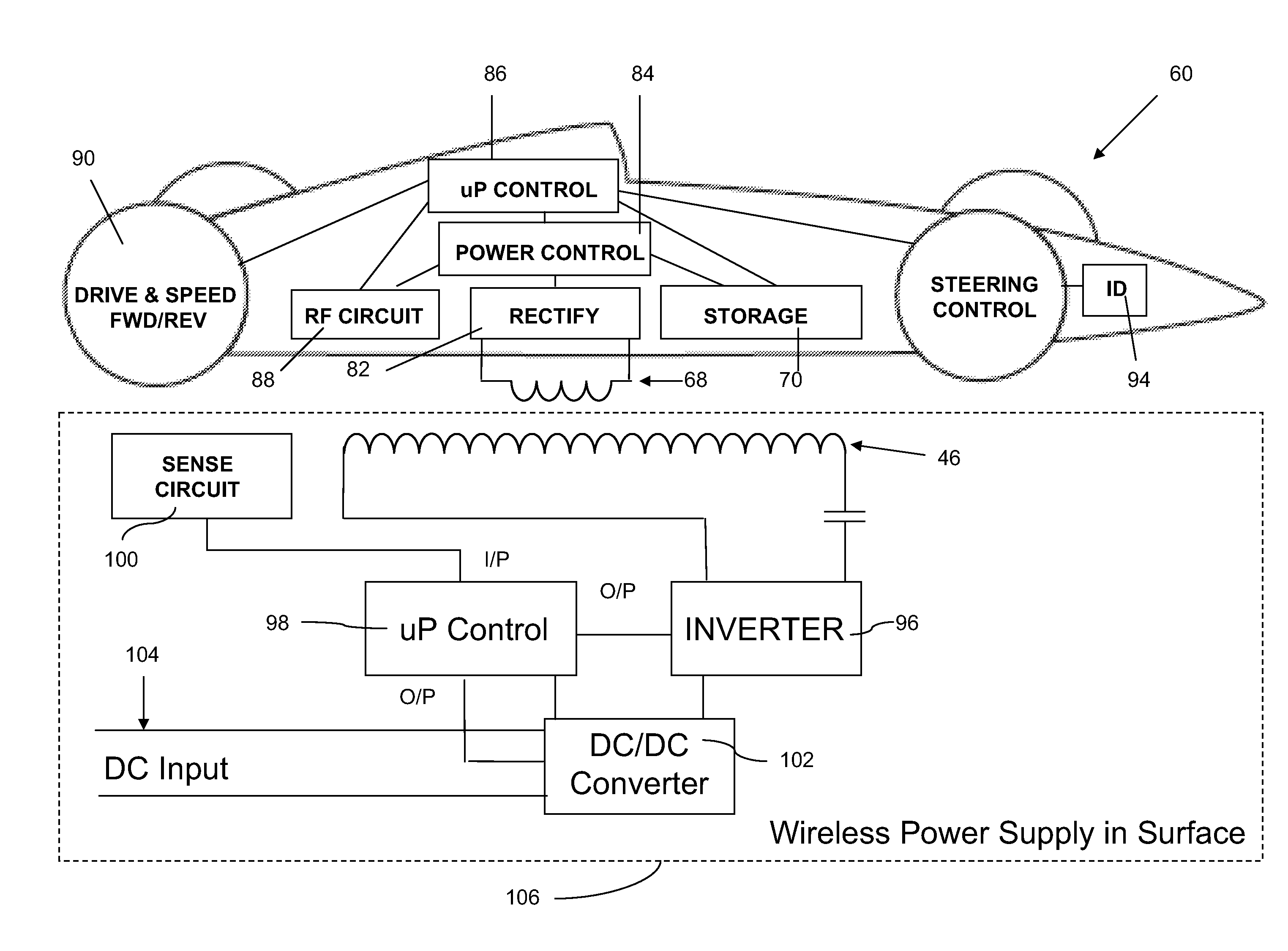
The present invention is a toy vehicle system that eliminates electrical contacts on both the vehicle and track, replacing them with inductive elements. This eliminates the risk of electrical shocks and allows for wireless remote control operation. The system includes an inductive coil track portion with a primary inductive coil in proximity to the track surface, a toy vehicle with inductive secondary coil for receiving electrical power, and a power supply for powering the track. The toy vehicle can operate at different speeds and has steering controls. It also includes a computer control system for monitoring performance, training purposes, and providing entertainment variables. The invention also includes a track portion with a primary inductive coil and a sensor to detect the presence of a vehicle and power the vehicle's secondary inductive coil. The toy vehicle can be equipped with a secondary inductive coil, a primary inductive coil power station, and a remote control device for operating the toy vehicle. The invention allows for safer and wireless operation of toy vehicles.

Problems solved by technology

Thus, good electrical conductivity and physical contact is required throughout the entire track surface, or the cars may stop or perform erratically.
Another issue with the track segments involves the connection of the track segments to each other.
Over time, these contact areas between track segments can become worn and the conductivity degraded.
Additionally, the wires embedded in the track surface can oxidize while exposed to air, reducing the conductivity possible and reducing performance.
This is time-consuming and can be difficult, depending on the length of track to be cleaned.

Method used


Image

  • Inductive toy vehicle
  • Inductive toy vehicle
  • Inductive toy vehicle

Examples


Embodiment Construction

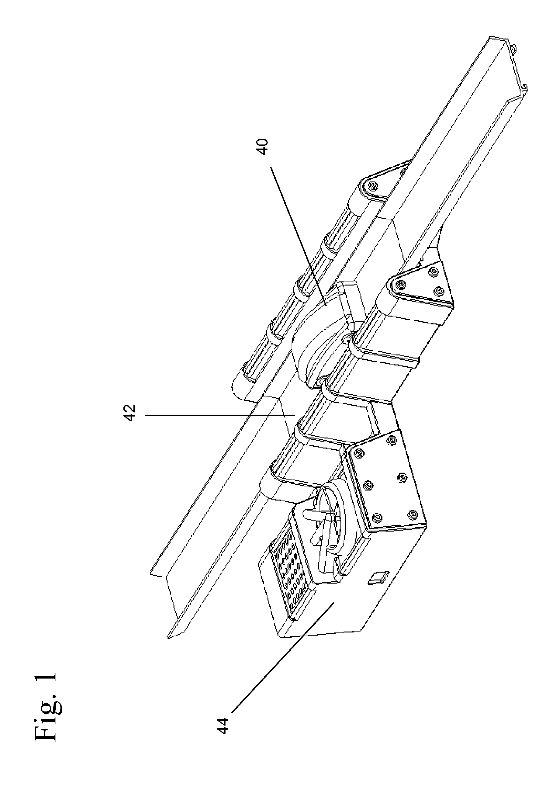
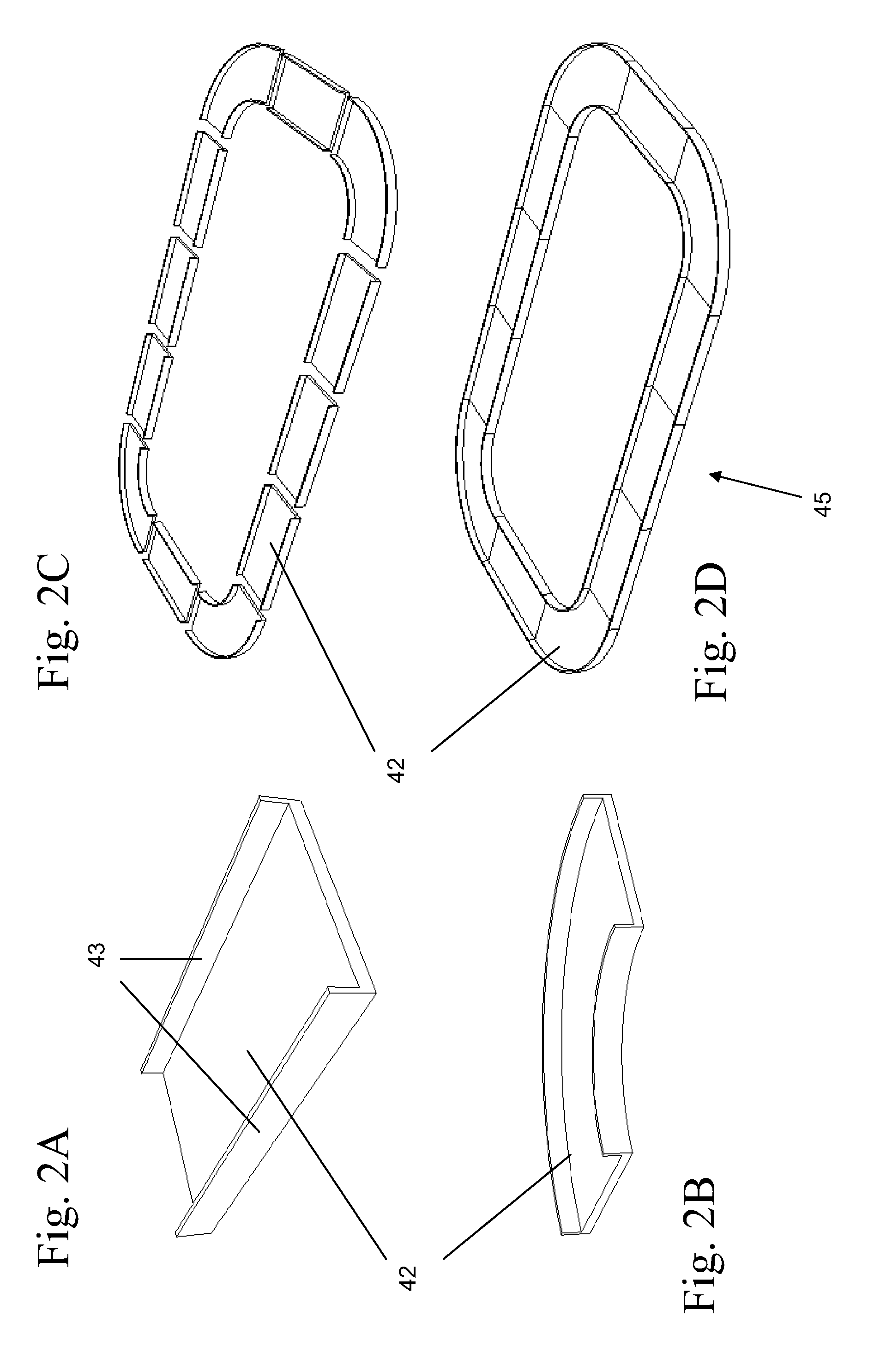
[0060]With reference to FIG. 1, a toy vehicle system including an inductively powered toy vehicle 40, at least one track segment 42, and an associated control module 44 is shown. The vehicle 40 is drivable on a track including at least one segment 42 having a wireless power supply to generate an inductive field, wherein the vehicle 40 receives power from the inductive field when it traverses the track segment 42. Though shown as adapted for use on a circuit formed of multiple interconnected track segments 42, the toy vehicle 40 may also be used with only a single track segment 42 in combination with any suitable driving surface. With reference to FIGS. 2A-2D, track segments 42 may be straight, curved, a combination of both, or other shapes, such as an intersection or a pit road track segment. Plastic or other formable material may be used to construct the track segments, which optionally include connectors (not shown) to join other track segments together. These connectors allow for...


PUM


Abstract

An inductively powered toy vehicle and an associated track with inductive charging segment. The vehicle may include a secondary coil, a drive motor, an electrical power storage device connected between said secondary coil and said drive motor, and a wireless communications unit. The charging segment may include a primary coil, a sense circuit operable to detect the presence of the vehicle based on a change in the detected impedance of the primary coil, and a power control unit operable to provide a time-varying current to the primary coil when the vehicle traverses the charging segment. The primary coil is positioned within the race track adjacent the track upper surface. The vehicle drive motor may be operable at first and second speed settings, and a remote control device can provide operating instructions to the vehicle wireless communications unit.

Description

[0001]This application claims the benefit of U.S. Provisional Application No. 61 / 116,908, filed Nov. 21, 2008, and entitled “Inductive Toy Vehicle.”BACKGROUND OF THE INVENTION[0002]The present invention relates to providing inductive power to toy vehicles.[0003]Electrically powered race track toys are known. Some are intended for use on a grooved track surface, and are known as slot cars. These toy vehicles or slot cars are designed for use on a segmented electrified track surface that is equipped with a slot, for accepting a guide pin attached to the car, and a pair of electrical contacts on either side of slot, also on the bottom of the car, for contacting matching wires embedded in the track to provide power to the car's electric motor. Other cars are slot-less, and are retained on the track segments by curbs or walls on either side. In the case of slot-less cars, most if not all of the track surface is equipped with electrical contacts to provide power to the car's electric moto...

Claims


Application Information

Patent Timeline
Patent Type & Authority Patents(United States)
IPC IPC(8): A63H18/00
CPCA63H17/26A63H18/12A63H19/24A63H30/04A63H18/02
Inventor BAARMAN, DAVID W.BYLSMA, RICHARD B.NGUYEN, HAI D.TAYLOR, JOSHUA B.STONER, JR., WILLIAM T.
Owner PHILIPS IP VENTURES BV
Learn More