

Differential signal transmission cable
a transmission cable and signal technology, applied in the direction of power cables, cables, insulated conductors, etc., can solve the problems of differential-to-common-mode conversion quantity (i.e., the conversion quantity of differential-to-common-mode to common-mode) may increase, and achieve the effect of suppressing the loosening of binding tap
- Summary
- Abstract
- Description
- Claims
- Application Information
AI Technical Summary
Benefits of technology
Problems solved by technology
Method used
Image

Examples
first embodiment
[0044]Structural Outline of Differential Signal Transmission Cable 1
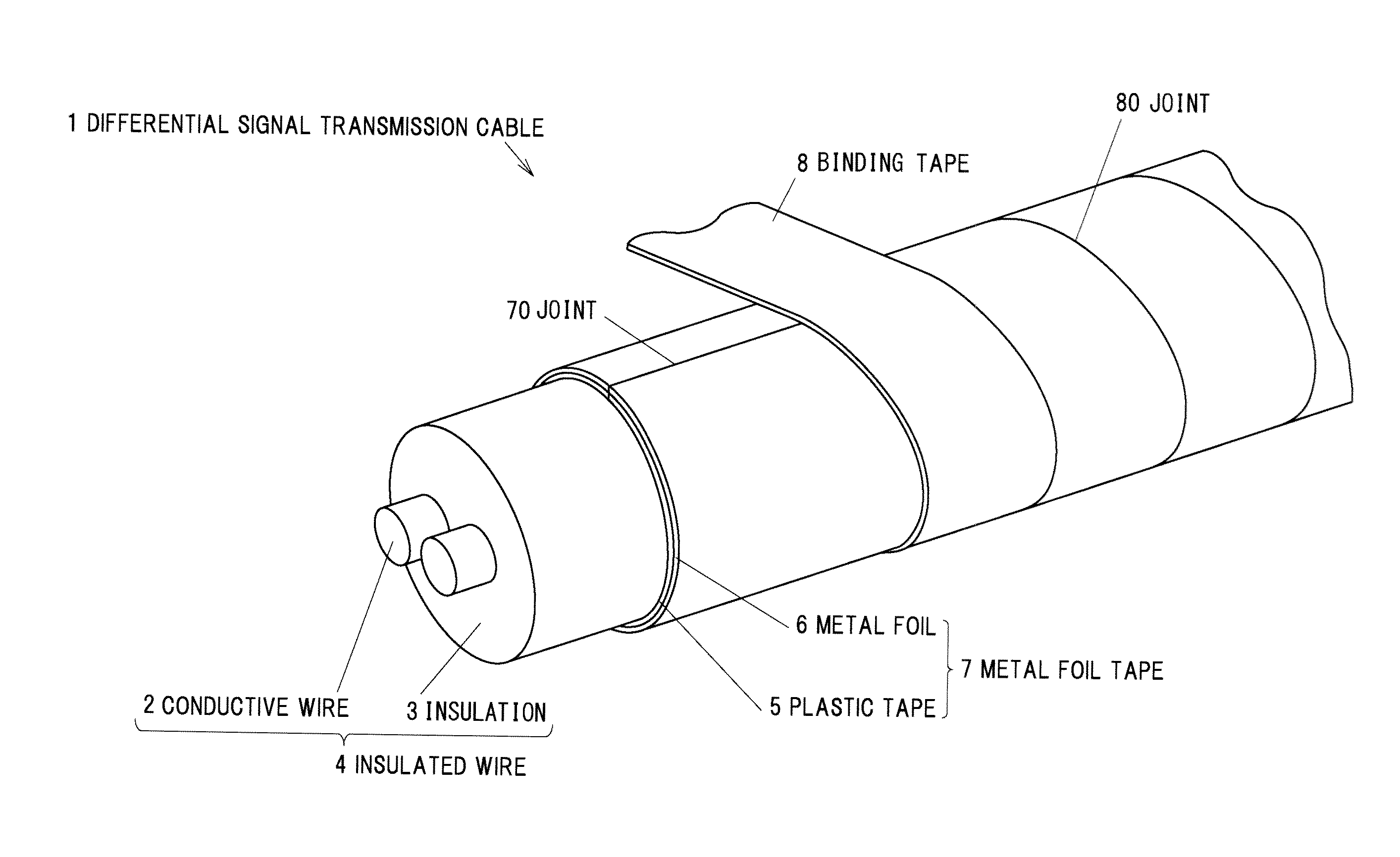
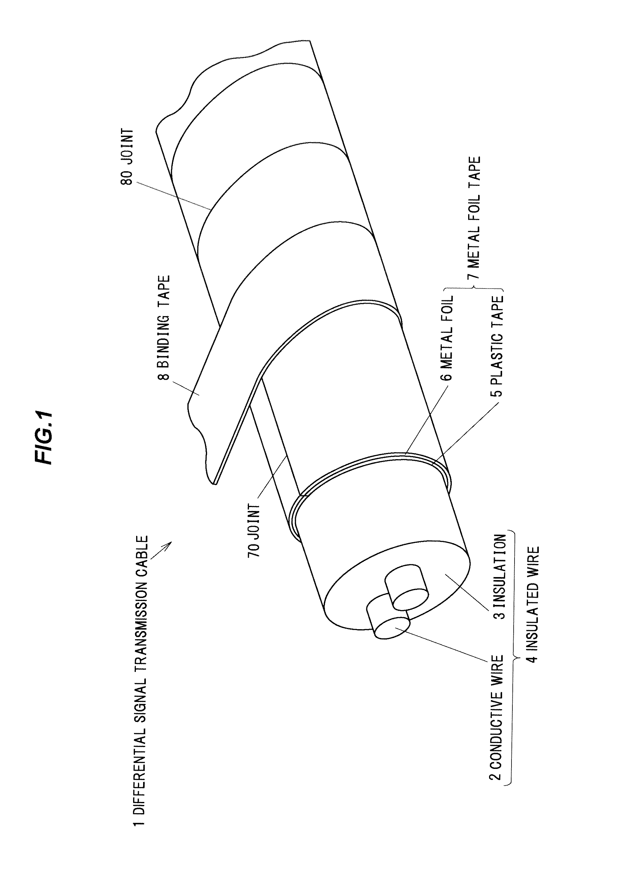
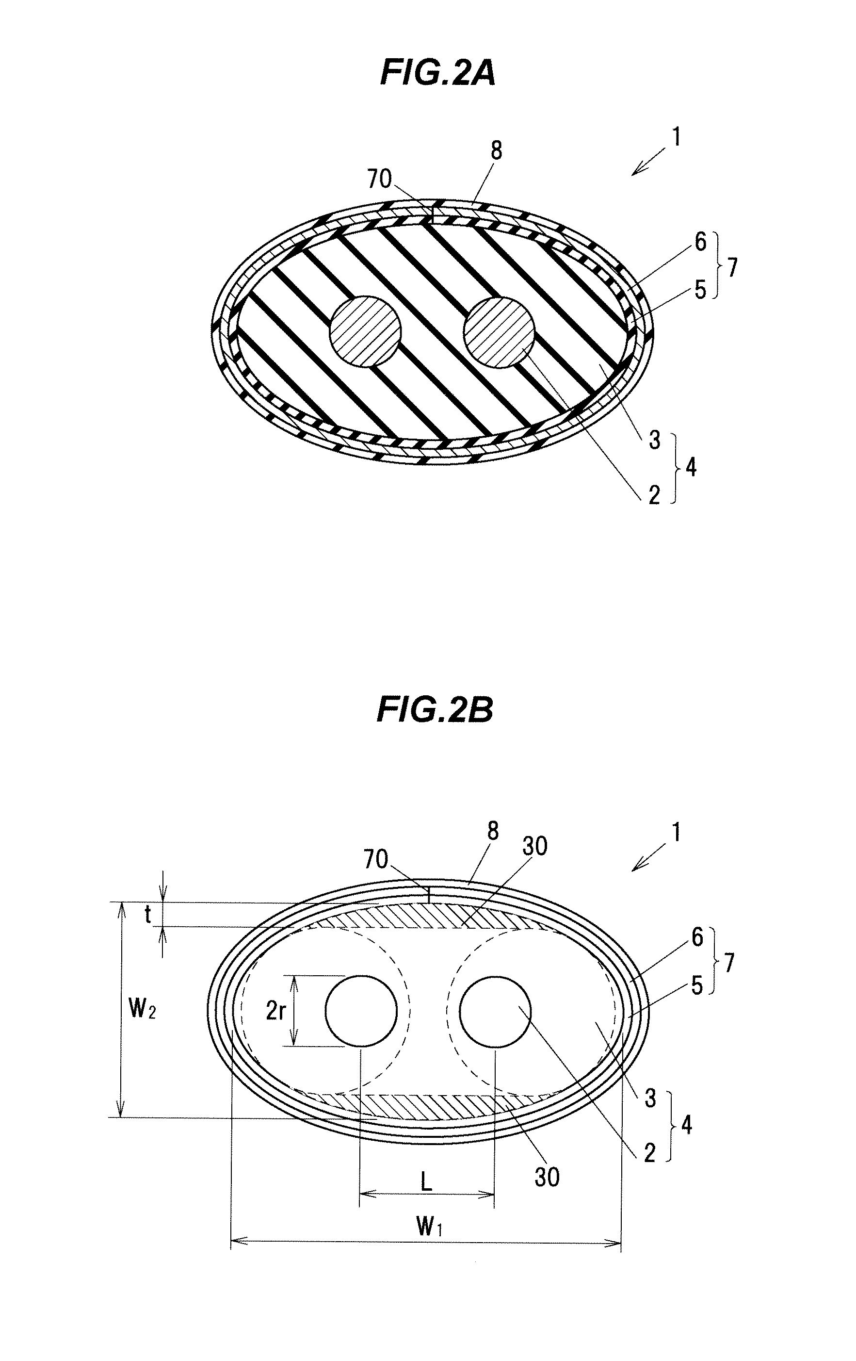
[0045]FIG. 1 is a perspective view showing a differential signal transmission cable 1 in a first embodiment. FIG. 2A is a cross sectional view showing the differential signal transmission cable 1 in the first embodiment which is cut in a transverse direction (a direction perpendicular to a longitudinal direction) and FIG. 2B is a schematic diagram illustrating a cross section of the differential signal transmission cable 1 which is cut in a transverse direction. Two circles indicated by a dotted line in FIG. 2B are to facilitate explanations and show cross sectional shapes of insulated wires which are used for making a cable having a transverse cross sectional shape equivalent to that of the differential signal transmission cable 1. Hereinafter, a cross section means a cross section which is cut in a transverse direction unless otherwise indicated.
[0046]The differential signal transmission cable 1 is, e.g., a cable ...
second embodiment
[0089]The second embodiment is different from the first embodiment in that the outer circumferential shape of the transverse cross section of the insulation 3 is an ellipse shape.
[0090]FIG. 5A is a transverse cross sectional view showing a differential signal transmission cable 1 in a second embodiment and FIG. 5B is a diagram relating to the maximum value and the minimum value of curvature radius. In FIG. 5B, the horizontal axis is the x-axis and the vertical axis is the y-axis. In the ellipse, a major axis is on the x-axis and a minor axis is on the y-axis. It should be noted that, in each of the following embodiments, portions having the same structure and function as those in the first embodiment are denoted by the same reference numerals and explanations thereof will be omitted.
[0091]In the differential signal transmission cable 1 of the second embodiment, the outer circumferential shape of the insulation 3 is an ellipse shape having foci A and B. Other configurations are the s...
third embodiment
[0100]The third embodiment is different from the first and second embodiments in that a degree of foaming within the insulation 3 is different in an internal portion and in an outer peripheral portion.
[0101]FIG. 6 is a cross sectional view showing a differential signal transmission cable in a third embodiment. In FIG. 6, a region surrounded by an outer periphery of the insulation 3 and a dotted line is an insulation layer 31.
[0102]In the differential signal transmission cable 1 of the third embodiment, a degree of foaming within the insulation 3 is different in an internal portion and in an outer peripheral portion. Other configurations are the same as the differential signal transmission cable 1 in the first embodiment. The degree of foaming is, e.g., 50% in the internal portion and several % in the insulation layer 31
[0103]The insulation layer 31 of the insulation 3 has a degree of foaming lower than that of the internal portion of the insulation 3. In other words, in the insulati...
PUM
| Property | Measurement | Unit |
|---|---|---|
| diameter | aaaaa | aaaaa |
| width W2 | aaaaa | aaaaa |
| width W2 | aaaaa | aaaaa |
Abstract
Description
Claims
Application Information