
Method and apparatus for directional acoustic fitting of hearing aids

a technology for acoustic fitting and hearing aids, applied in the field of hearing aids, can solve the problems of reducing the ability to perceive sound direction, using hearing aids, further reducing the perception of sound direction, etc., and achieve the effect of accurately determining the individual's perception of loudness differences, accurate measurement, and improved signal-to-noise ratio 3 db

Active Publication Date: 2013-10-08
DEAN ROBERT GARY ANDERSON AS TRUSTEE OF THE D L ANDERSON FAMILY TRUST
View PDF34 Cites 10 Cited by
  • Summary
  • Abstract
  • Description
  • Claims
  • Application Information

AI Technical Summary

Benefits of technology

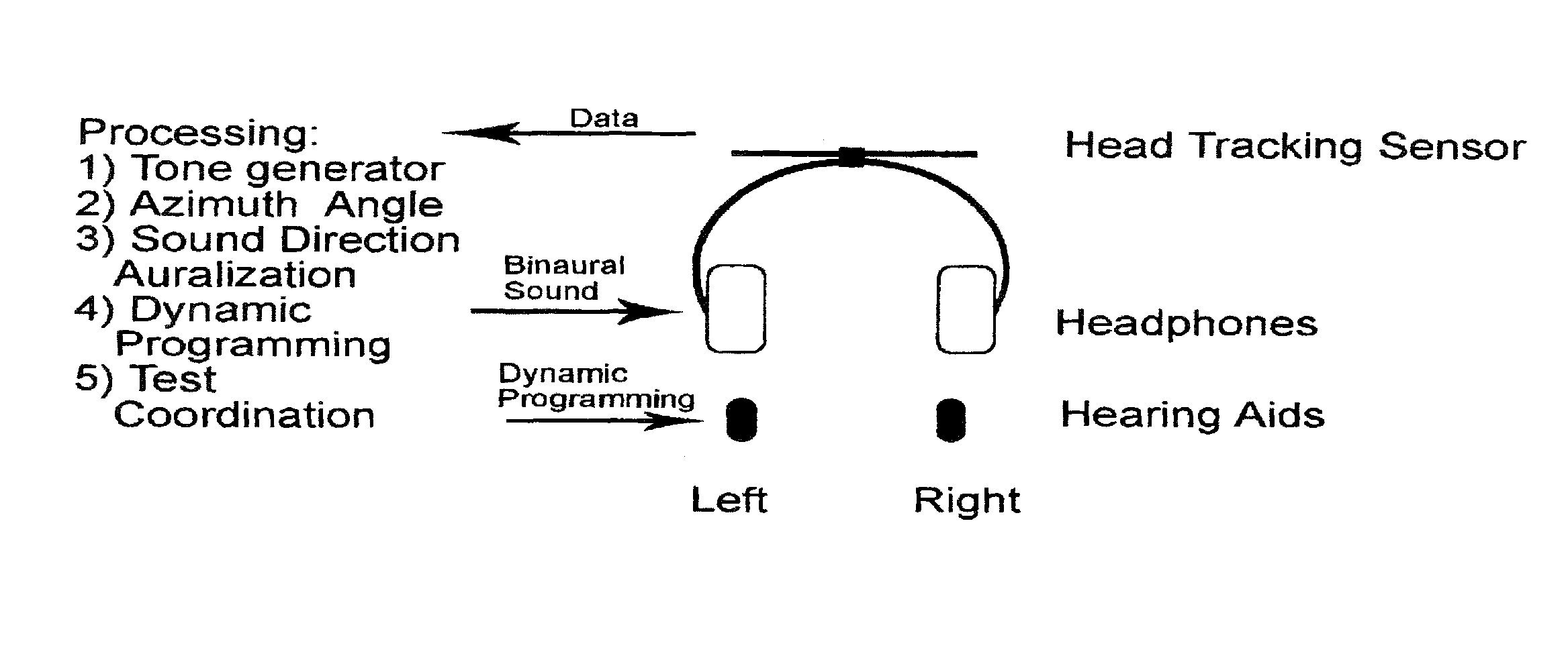
The present invention is a hearing aid fitting system that uses precise sound localization to improve the directional hearing of individuals. By detecting the orientation of the person's head and making modifications to the sound signals, the system can create a realistic "virtual presence" of the sound source for the person. This results in a more natural and effective listening experience for users of the hearing aid. In one embodiment, a pair of stereo headphones is used to measure the head's orientation and the system adjusts the sound signals accordingly to match the person's unique needs. This ensures that the hearing aid's directional performance is optimized for the individual being fitted. The system automatically compensates for changes in the person's position and head movements, resulting in a seamless and stable listening experience.

Problems solved by technology

The use of hearings aids, however, will often times diminish the ability to perceive sound direction.
Improper hearing aid fitting can further diminish sound direction perception.
This is an obvious disadvantage to the use of hearing aids.
It has been universally accepted through digital signal processing research that signal processing alone will not improve the intelligibility of a signal in noise, especially in the case where the signal is one person talking and the noise is other people talking (i.e., “the cocktail party effect”).
With currently available hearing aids, there is no way to communicate to the digital processor that the listener now wishes to turn his / her attention from one talker to another, thereby reversing the roles of signal and noise sources.
Because directional microphones are subject to the effects of back and / or side lobes, a deficiency in such hearing aids is a result of these effects in directional microphone sound reception.
Another deficiency in the current state of hearing aids related to improving speech recognition in noisy environments is directly related to the current fitting protocols used to acoustically fit hearing aids to a hearing impaired individual.
The current fitting process often results in substantial loss of localization perception for the user by making only a fraction of the speech cues available.
In addition, the maximum loudness discomfort levels of the patient are not measured or accounted for in current hearing aid fitting protocols.
Loudness recruitment is a condition that results in an abnormally-rapid increase in loudness perception with relatively small increases in sound levels above the hearing threshold of the hearing impaired person.
For example, a person with loudness recruitment may not be able to hear high frequency sounds below 50 dBSPL, but may find any sounds above 80 dBSPL uncomfortable and even distorted.
For such a hearing impaired individual, recruitment can mean a collapse of loudness tolerance and the feeling of distortion of loud sounds.
This phenomenon occurs because at some decibel level, the normal hair cells adjacent to the damaged hair cells (corresponding to the frequency of a hearing loss) are “recruited.” At the decibel level at which these recruited hair cells are triggered, the perceived loudness quickly increases and often causes hearing discomfort.
In practice the ABLB test is rarely performed by audiologist while fitting hearing aids because of the time it takes to perform such tests using current testing methods and devices and the lack of use of such test result data by current systems for hearing aid fitting.
As current methods of hearing aid fitting do not typically account for loudness recruitment, patients having such a condition are often fitted with hearing aids that become uncomfortable to wear because the dynamic range of hearing is so easily exceeded by the hearing aid.
Amplification that is sufficient to make sub-threshold sounds audible, however, will tend to make higher-level sounds uncomfortably loud.
In addition, because of the techniques employed in current hearing testing systems, it is also the case that the best amplification compression methods will not be properly configured for a given patent because the patient has not been properly tested in order to generate the correct gain curves for the hearing aids.
As such, a major deficiency of most hearing aid fitting protocols is the inaccurate test results that are often attained that are used as the basis for a hearing aid fitting.
Indeed, when such verbal test methods are used, discrepancies of 10 dB or more are not uncommon and have been reported to be found in 36% of threshold of hearing measurements.
Based on the known error rate of 36%, it is the case that six or seven measurements in such a test are likely in error.
Another major disadvantage of measurements obtained using a traditional transducer is that results are not interchangeable with measurements taken with another transducer for a given individual.
Still another deficiency of current audiometers is found within the audiometer standards.
Moreover, spectral group velocities can shift and distort based on frequency and amplitude weighting and amplification through the non-ideal hearing aid components (for example: damping via ferrofluids purposely designed into some receiver-speakers to reduce unintended oscillations).

Method used


Image

  • Method and apparatus for directional acoustic fitting of hearing aids
  • Method and apparatus for directional acoustic fitting of hearing aids
  • Method and apparatus for directional acoustic fitting of hearing aids

Examples


Embodiment Construction

[0068]Those of ordinary skill in the art will realize that the following description of the present invention is illustrative only and not in any way limiting. Other embodiments of the invention will readily suggest themselves to such skilled persons.

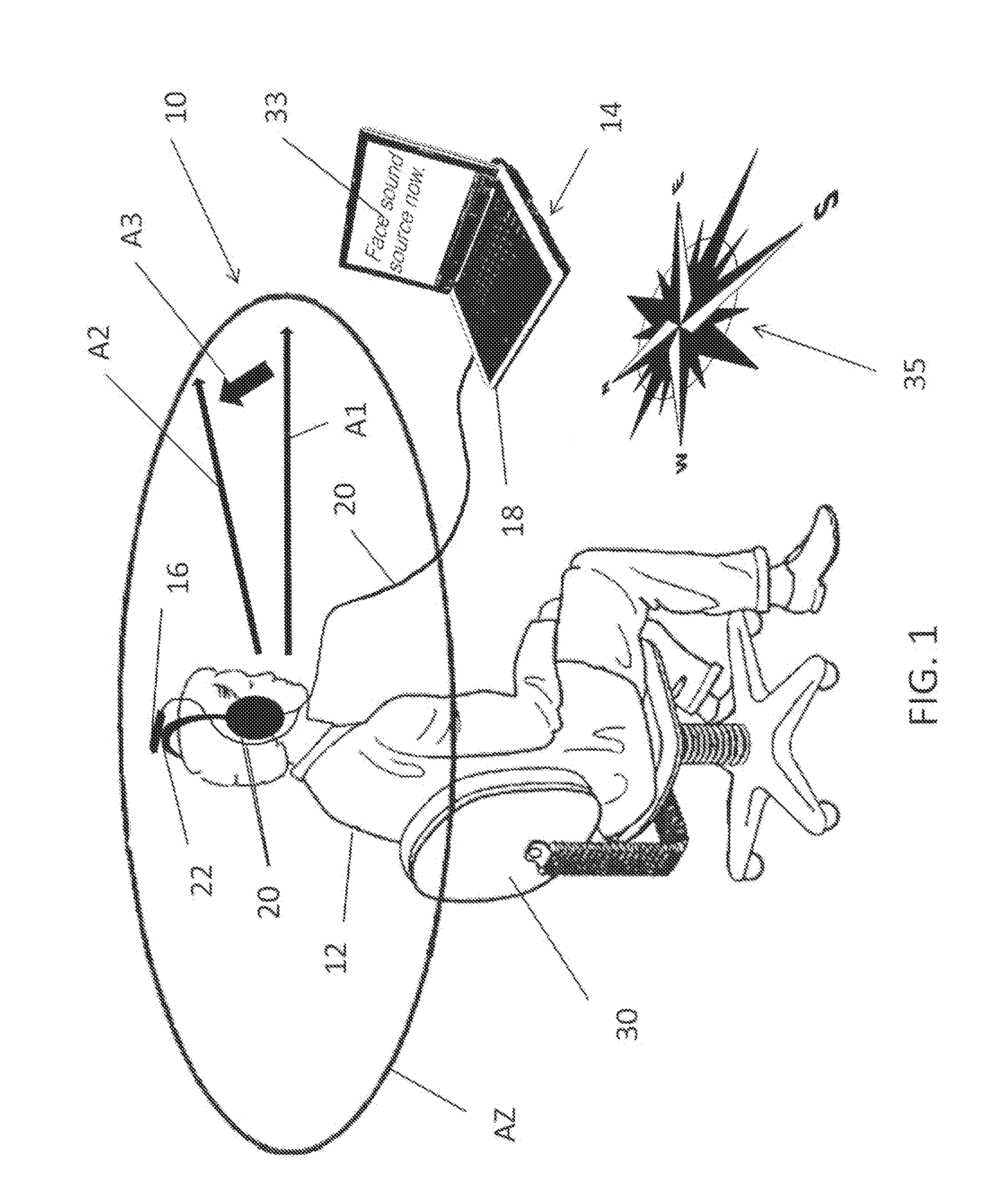
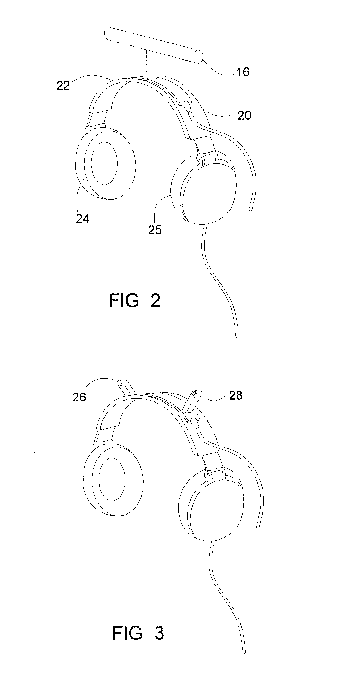
[0069]FIG. 1 illustrates a hearing aid fitting system, generally indicated at 10 in accordance with the principles of the present invention. An assessment of sound direction perception of an individual 12 is accurately made across a broad dynamic range in multiple frequency bands. Unlike prior art fitting systems, the tones presented to the individual 12 in the hearing loss assessment and fitting system 10 of the present invention are generated by an audiometer 14, which includes a head azimuth detecting device 16 that is measured in near real time by a computer 18 or other processing device that also provides corresponding binaural feedback and affirmation to the individual being fitted via a pair of headphones 20. The present hearing ...


PUM


Abstract

A method of acoustically fitting a hearing aid comprises providing a plurality of audible tones, each having a predetermined frequency through stereo headphones. The tones are provided at specific sound pressure in each ear. The patient changes the relative sound pressure in each ear until a perceived direction of source of the tone is in front of the patient. The amplification or attenuation requirements of a hearing aid are modified based on the difference in the sound pressures required for the left and right ears of the patient for perceived directional sameness for each frequency band-pass channel.

Description

CROSS-REFERENCE TO RELATED APPLICATION[0001]The present invention claims priority to U.S. Provisional Patent Application Ser. No. 61 / 185,531 filed on Jun. 9, 2009, to Dean Robert Gary Anderson, the entirety of which is incorporated by this reference.BACKGROUND[0002]1. Field of the Invention[0003]The present invention relates generally to hearing aids used by the hearing impaired and methods for acoustically fitting such hearing aids based on the person's specific hearing capabilities at various sound frequencies and amplitudes. More specifically, the present invention relates to an apparatus and method for configuring or programming hearing aids based on the person's perceived position of sources of sounds at various frequencies and amplitudes.[0004]2. State of the Art[0005]Individuals with at least some hearing capacity can determine sound direction. When both ears are involved in this localization process (binaural hearing), sound direction is perceived by differences in both soun...

Claims


Application Information

Patent Timeline
Patent Type & Authority Patents(United States)
IPC IPC(8): H04R29/00H04R5/00
CPCA61B5/11A61B5/6803H04R25/70H04S7/301A61B5/12H04R25/40H04R2430/03
Inventor ANDERSON, DEAN ROBERT GARY
Owner DEAN ROBERT GARY ANDERSON AS TRUSTEE OF THE D L ANDERSON FAMILY TRUST
Learn More