Thermoacoustic device

a technology of thermoacoustic devices and sound waves, applied in the field of thermoacoustic devices, can solve the problems of sound wave generation, easy short circuit, and the inability of the loudspeaker to generate sound

Active Publication Date: 2013-10-08
BEIJING FUNATE INNOVATION TECH
View PDF9 Cites 15 Cited by
  • Summary
  • Abstract
  • Description
  • Claims
  • Application Information

AI Technical Summary

Benefits of technology

[0007]A loudspeaker based on the thermoacoustic effect was created by Fan et al. (“Flexible, Stretchable, Transparent Carbon Nanotube Thin Film Loudspeakers”, Nano Letters, Vol. 8, No. 12, p 4539-4545 (2008)). The loudspeaker includes a carbon nanotube film acting as a thermoacoustic element. The carbon nanotube film is flexible, and easily shaped. Metal has good plasticity properties and can be formed into various shapes. The methods for manufacturing metal are mature. Thus, the metal generally can form a metal supporter to support a flexible film. However, the carbon nanotube film and metal both have electrically conductive properties, if the carbon nanotube film is located on the metal supporter, it will be easy short circuit. Thus, the loudspeaker cannot generate sound. Therefore, the thermoacoustic device is not suitable for employing a metal supporter.

Problems solved by technology

The heating of the medium causes thermal expansion and produces pressure waves in the surrounding medium, resulting in sound wave generation.
However, the carbon nanotube film and metal both have electrically conductive properties, if the carbon nanotube film is located on the metal supporter, it will be easy short circuit.
Thus, the loudspeaker cannot generate sound.
Therefore, the thermoacoustic device is not suitable for employing a metal supporter.

Method used


Image

  • Thermoacoustic device
  • Thermoacoustic device
  • Thermoacoustic device

Examples


Embodiment Construction

[0014]The disclosure is illustrated by way of example and not by way of limitation in the figures of the accompanying drawings in which like references indicate similar elements. It should be noted that references to “an” or “one” embodiment in this disclosure are not necessarily to the same embodiment, and such references mean at least one.

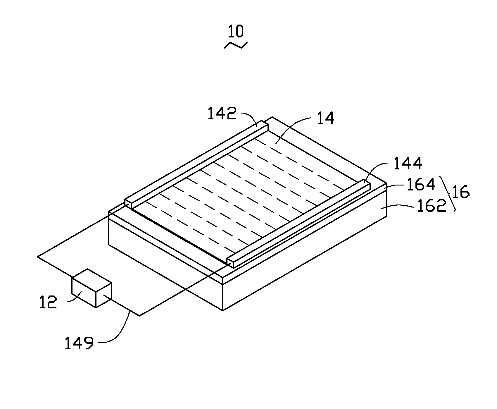
[0015]Referring to FIG. 1, a thermoacoustic device 10 according to one embodiment includes a signal element 12, a sound wave generator 14, a first electrode 142, a second electrode 144, and a support element 16. The sound wave generator 14 is disposed on the support element 16. The support element 16 supports the sound wave generator 14. The first electrode 142 and the second electrode 144 are located apart from each other, and are electrically connected to the sound wave generator 14. The first electrode 142 and the second electrode 144 are electrically connected to the signal element 12. The first electrode 142 and the second electrode 144 inpu...


PUM


Abstract

A thermoacoustic device includes a sound wave generator, a signal element and a support element. The sound wave generator includes a carbon nanotube structure. The signal element is configured to transmit a signal. The carbon nanotube structure is configured to receive the signal and generate a sound wave. The support element includes a metal substrate and an insulating layer located on the metal substrate. The insulating layer is sandwiched between the metal substrate and the sound wave generator. The thermoacoustic device further includes two electrodes electrically connected to the carbon nanotube structure.

Description

RELATED APPLICATIONS[0001]This application claims all benefits accruing under 35 U.S.C. §119 from China Patent Application No. 201010167401.8, filed on May 10, 2010 in the China Intellectual Property Office, the disclosure of which is incorporated herein by reference.BACKGROUND[0002]1. Technical Field[0003]The present disclosure relates to acoustic devices, particularly, to a thermoacoustic device.[0004]2. Discussion of Related Art[0005]Acoustic devices generally include a signal element and a sound wave generator. The signal element inputs signals to the sound wave generator such as a loudspeaker. Loudspeaker is an electro-acoustic transducer that converts electrical signals into sound.[0006]Thermoacoustic effect is a conversion between heat and acoustic signals. When signals are inputted into a thermoacoustic element, heating is produced in the thermoacoustic element according to the variations of the signal and / or signal strength. Heat is propagated into surrounding medium. The h...

Claims


Application Information

Patent Timeline
Patent Type & Authority Patents(United States)
IPC IPC(8): H04R25/00
CPCH04R5/023H04R23/002
Inventor WANG, YU-QUANQIAN, LIFENG, CHENLIU, LIANG
Owner BEIJING FUNATE INNOVATION TECH
Why Eureka
Try Eureka