
Power supply and demand control apparatus and power supply and demand control method

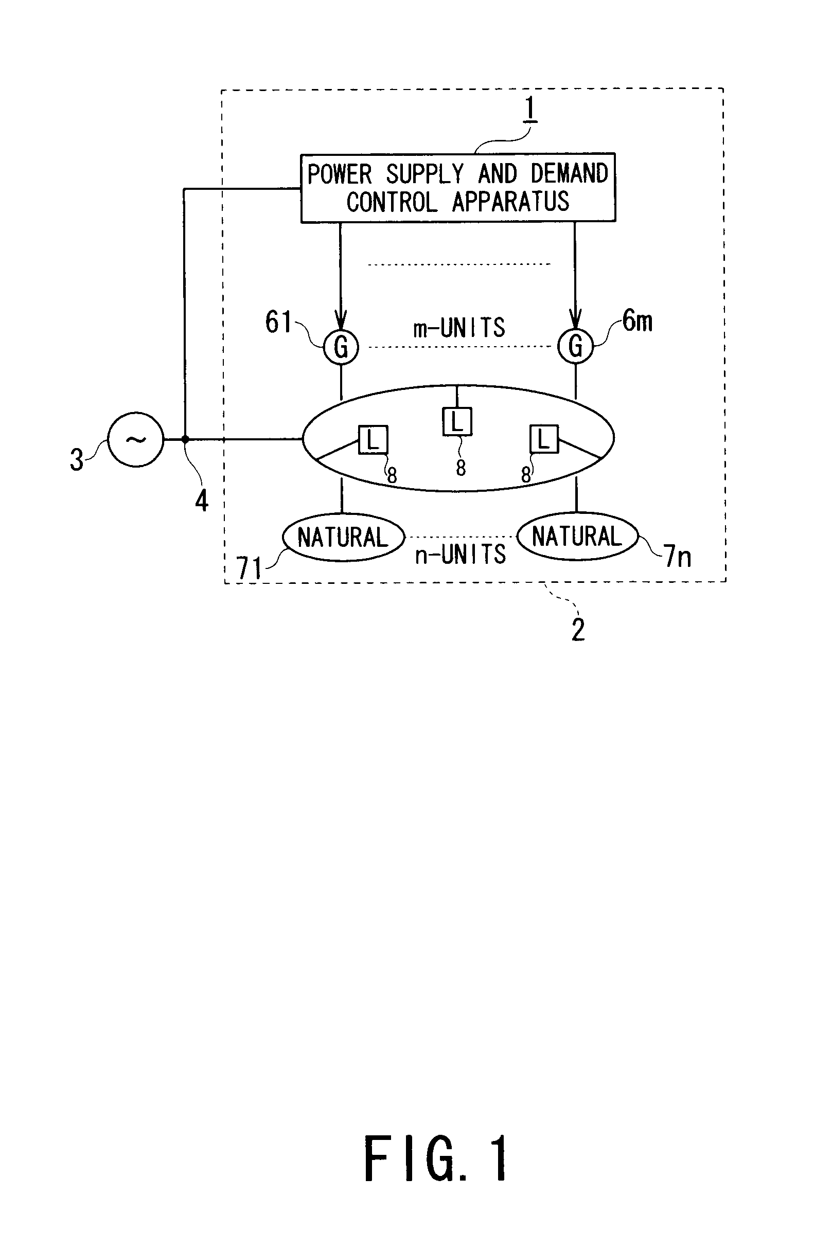
a technology of power supply and demand control and power supply and demand, which is applied in the integration of power network operation systems, process and machine control, instruments, etc., can solve the problems of large fluctuations in power generation of small-scale power systems such as microgrids, and it is more difficult for small-scale power systems to achieve supply-demand balancing

Inactive Publication Date: 2013-10-08
KK TOSHIBA
View PDF3 Cites 4 Cited by
  • Summary
  • Abstract
  • Description
  • Claims
  • Application Information

AI Technical Summary

Benefits of technology

[0013]In view of the circumstances encountered in the conventional techniques mentioned above, an object of the present invention is to provide a power supply and demand control apparatus and a power supply and demand control method which can ensure supply-demand balancing of electric energy at any given location approximately every few tens of minutes as well as ensure supply-demand balancing in shorter cycles when any difference arises between estimated values and actual values of load power or between estimated values and actual values of power output of a natural energy generation apparatus, in a small-scale power system.
[0019]a first supply-demand balancing control unit that corrects the electric power flow target calculated by the power generation planning unit so as to eliminate the deviations between the total power output of the distributed power sources and the load power in the power system to thereby ensure supply-demand balancing of electric energy in a given amount of time at the electric power flow measuring location,
[0025]a second supply-demand balancing control unit that corrects and outputs the electric power flow target corrected by the first supply-demand balancing control unit so as to eliminate the deviations between the total power output of the distributed power sources and the load power of the power system and ensure the supply-demand balancing in a period shorter than a supply-demand balancing period ensured by the first supply-demand balancing control unit, and
[0032]a first supply-demand balancing control step of correcting the electric power flow target calculated by the power generation planning step, so as to eliminate the deviations between the total power output of the distributed power sources and the load power in the power system to thereby ensure supply-demand balancing of electric energy in a given amount of time at the electric power flow measuring location,
[0038]a second supply-demand balancing control step of correcting and outputting the electric power flow target corrected by the first supply-demand balancing control step, so as to eliminate the deviations between the total power output of the distributed power sources and the load power of the power system and ensure supply-demand balancing in shorter periods than a supply-demand balancing period ensured by the first supply-demand balancing control step, and
[0041]The power supply and demand control apparatus and power supply and demand control method according to the present invention perform control so as to ensure the supply-demand balancing of the electric energy at any given location including a linking point between a power system to which the present invention is applied and another power system approximately every few tens of minutes as well as ensure the supply-demand balancing in shorter cycles (approximately every few minutes). Accordingly, the power supply and demand control apparatus and the power supply and demand control method according to the present invention can improve the supply-demand balancing performance compared to the conventional power supply and demand control apparatus and methods.

Problems solved by technology

However, small-scale power systems such as microgrids are subject to large fluctuations in the power generation due to reliance on the natural energy generation apparatus and because of limited demand.
Therefore, it is more difficult for the small-scale power systems to achieve the supply-demand balancing in short time periods than for medium- or large-scale power systems.

Method used


Image

  • Power supply and demand control apparatus and power supply and demand control method
  • Power supply and demand control apparatus and power supply and demand control method
  • Power supply and demand control apparatus and power supply and demand control method

Examples


first embodiment

[0056]A power supply and demand control apparatus and a power supply and demand control method (hereinafter referred to as first power supply and demand control apparatus and first power supply and demand control method, respectively) according to a first embodiment of the present invention will be described.

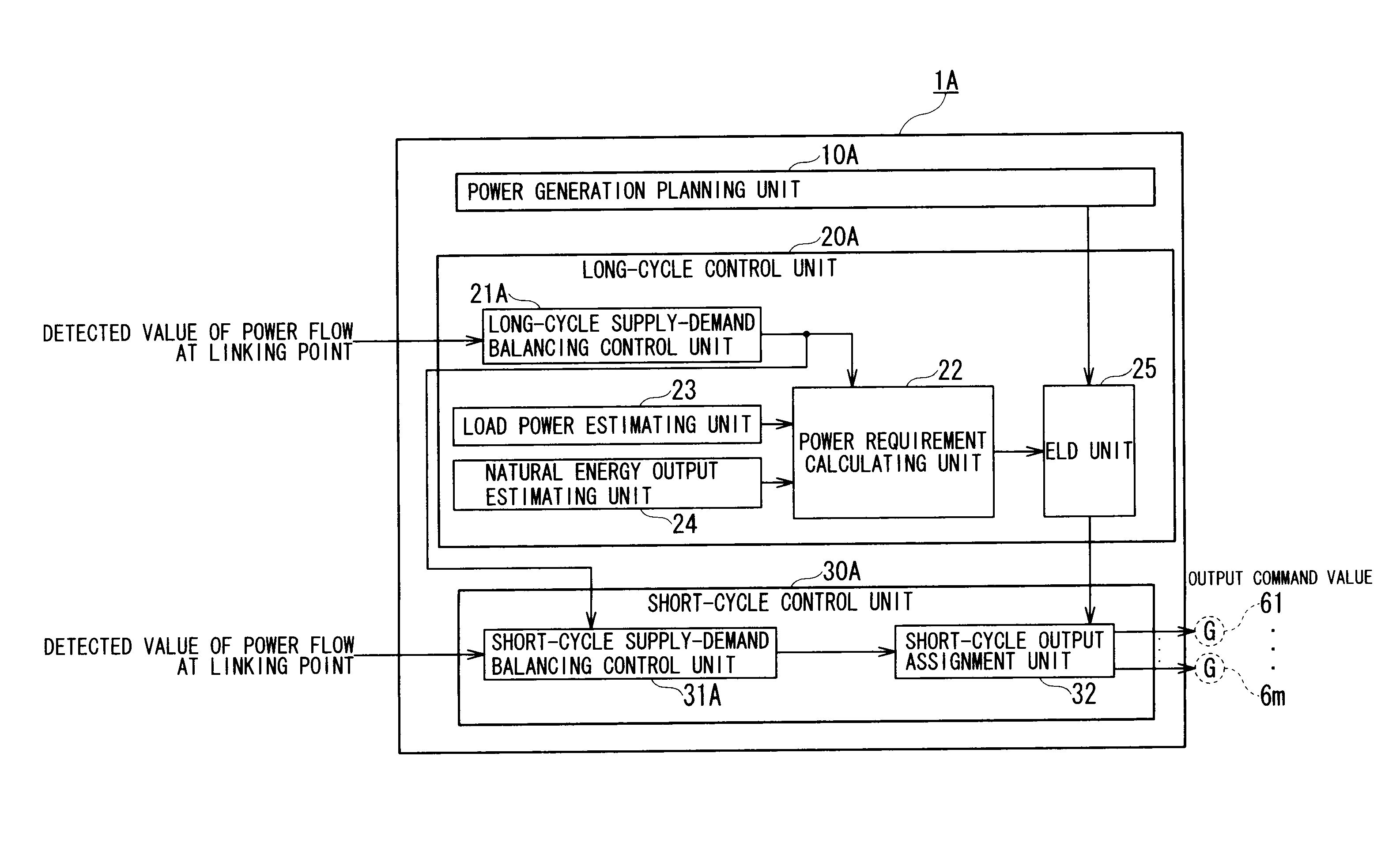
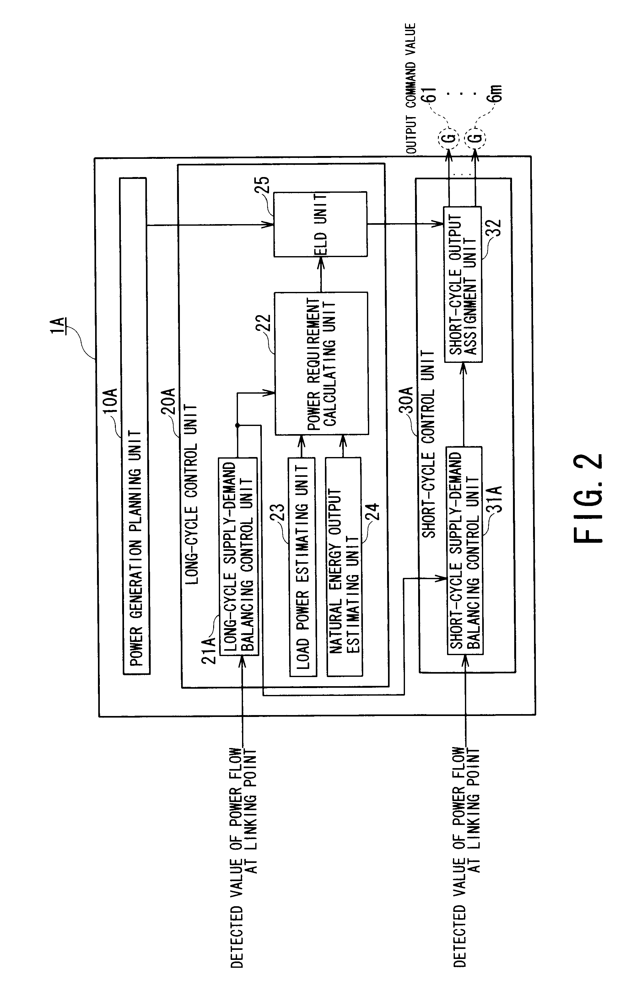
[0057]FIG. 2 is a block diagram schematically showing a configuration of the power supply and demand control apparatus (first power supply and demand control apparatus) 1A according to the first embodiment of the present invention.

[0058]As shown in FIG. 2, the power supply and demand control apparatus 1A includes a power generation planning unit 10A, long-cycle control unit 20A, and short-cycle control unit 30A. In the power supply and demand control apparatus 1A shown in FIG. 2, the long-cycle control unit 20A in turn includes a long-cycle supply-demand balancing control unit 21A, a power requirement calculating unit 22, a load power estimating unit 23, a natural energy output ...

second embodiment

[0091]A power supply and demand control apparatus and a power supply and demand control method (hereinafter referred to as a second power supply and demand control apparatus and a second power supply and demand control method, respectively) according to a second embodiment of the present invention will be described with reference to FIG. 5.

[0092]FIG. 5 is a block diagram schematically showing a configuration of the power supply and demand control apparatus (second power supply and demand control apparatus) 1B according to the second embodiment of the present invention, and more specifically, a long-cycle supply-demand balancing control unit 21B and the short-cycle supply-demand balancing control unit 31B of the second power supply and demand control apparatus 1B.

[0093]The second power supply and demand control apparatus 1B shown in FIG. 5 is equipped with the long-cycle supply-demand balancing control unit 21B and the short-cycle supply-demand balancing control unit 31B instead of t...

third embodiment

[0115]A power supply and demand control apparatus and a power supply and demand control method (hereinafter referred to as a third power supply and demand control apparatus and a third power supply and demand control method, respectively) according to a third embodiment of the present invention will be described with reference to FIGS. 6 and 7.

[0116]FIG. 6 is a block diagram schematically showing a configuration of the power supply and demand control apparatus (third power supply and demand control apparatus) 1C according to the third embodiment of the present invention, and more specifically, a power generation planning unit 10C and a long-cycle supply-demand balancing control unit 21C of the third power supply and demand control apparatus 1C.

[0117]The third power supply and demand control apparatus 1C is equipped with a power generation planning unit 10C and a long-cycle supply-demand balancing control unit 21C instead of the power generation planning unit 10A and the long-cycle s...


PUM


Abstract

A power supply and demand control apparatus includes a power generation planning unit that calculates one day's power outputs of multiple distributed power sources and a power flow target of a linking point to another power system, a long-cycle control unit having a long-cycle supply-demand balancing control unit that performs control every few minutes so as to ensure the supply-demand balancing of electric energy in a given amount of time at the linking point in order to perform control for making deviations between total power output calculated by the power generation planning unit and load power in the power system constant, and a short-cycle control unit having a short-cycle supply-demand balancing control unit that performs similar control every few seconds. In the power supply and demand control apparatus, the long-cycle control unit and short-cycle control unit perform the supply-demand balancing control in a hierarchical fashion to determine output assignments of the distributed power sources.

Description

TECHNICAL FIELD[0001]The present invention relates to apparatus and method which perform control so as to keep electric power flow constant, and in particular, relates to a power supply and demand (supply-demand) control apparatus and power supply and demand (supply-demand) control method which control supply-demand balancing.BACKGROUND ART[0002]There is a small-scale power system, known as a microgrid or the like, which supplies power to customers in a specified region using multiple types of distributed power source installed in the specified region, including engine generators, turbine generators, power storage systems, fuel cells, and photovoltaic generation, wind-power generation, or other natural energy generation apparatus.[0003]When a small-scale power system is connected to a commercial power system of an electric power company, there includes either one of two methods, i.e., one: forward power flow which involves receiving power from the commercial power system, and the ot...

Claims


Application Information

Patent Timeline
Patent Type & Authority Patents(United States)
IPC IPC(8): G05D3/12
CPCH02J3/46H02J3/004Y04S10/50Y04S20/222Y02B70/3225
Inventor TOBA, KOJIKOBAYASHI, TAKENORIOGITA, YOSHIHIRONISHI, AKINORI
Owner KK TOSHIBA
Learn More