Method and apparatus for tracking conveyor belts

a technology of conveyor belts and tracking apparatuses, which is applied in the direction of conveyor parts, rollers, control devices of conveyors, etc., can solve the problems of ineffective correction of belt travel paths, increased mistracking of belts, and reduced friction between, so as to reduce the tension of the mistracking belt edge, increase the tension of the opposite lateral edge, and further mistracking of the belt

Active Publication Date: 2013-10-15
FLEXIBLE STEEL LACING
View PDF26 Cites 15 Cited by
  • Summary
  • Abstract
  • Description
  • Claims
  • Application Information

AI Technical Summary

Benefits of technology

[0008]In accordance with one aspect of the present invention, a conveyor belt tracking apparatus is provided having an elongate tracking roller that is pivotal about a downstream pivot connection for providing instability of the tracking roller about the pivot connection in response to mistracking of a conveyor belt traveling thereover in a generally longitudinal downstream direction. In this regard, upon mistracking of the conveyor belt toward an end portion of the tracking roller, the tracking roller pivots about the downstream pivot connection such that the end portion shifts downstream and laterally away from the pivot connection. In this manner, an energizing torque created by drag forces acting between the tracking roller and the mistracking edge of the belt traveling thereover is increased as the end portion of the tracking roller shifts laterally further away from the pivot connection. The pivot connection is also preferably inclined in an upstream direction such that as the one end portion shifts downstream and laterally away from the pivot connection in response to mistracking of the conveyor belt it also shifts upwardly to increase tension in the mistracking edge of the conveyor belt traveling thereover. In this regard, the tracking roller steers the conveyor belt toward a desired generally central belt travel path both by shifting the tracking roller so that the end portion toward which the belt is mistracking is positioned downstream of the opposite end portion of the tracking roller and by increasing the tension in the mistracking edge of the conveyor belt relative to the opposite edge of the conveyor belt. In addition, the present belt tracking apparatus does not require large energizing forces from engagement between the mistracking conveyor belt edge and adjacent sensor rollers to shift the end of the tracking roller upwardly against the weight of the conveyor belt.
[0010]More particularly, Applicants have discovered that in these prior systems, because the end portion toward which the belt mistracks shifts downwardly as it shifts downstream, the tension of the mistracking belt edge is decreased as it passes over the lowered end portion. In addition, the opposite end portion is shifted upwardly, actually increasing the tension in the opposite lateral edge of the belt. In this regard, the tension in the belt would urge the belt to mistrack even further. In other words, the conveyor belt would tend to shift toward the lower tension side which is the side of the belt that is lowered. Accordingly, it has been found that in these systems, when the friction at the interface between the conveyor belt and the idler roller is reduced the further mistracking of the belt caused by the downward shifting of the idler roller one end portion could greatly offset and reduce the corrective influence of the one end portion being shifted downstream to steer the conveyor belt and in some situations could actually overcome the steering effect of the downstream shifting of the one end portion, so that the belt is even further mistracked. In this regard, the present belt tracking apparatus includes the pivot connection inclined in the upstream direction to utilize the upward shifting of the end portion of the tracking roller to urge the conveyor belt away from the mistracking conveyor belt edge and toward the desired belt travel path.
[0011]In addition, as mentioned previously, the present belt tracking apparatus has the pivot connection positioned downstream of the tracking roller to provide dynamic instability of the tracking roller about the pivot connection to create sufficient energizing force to shift the end portion of the tracking roller to which the conveyor belt is mistracking upward against the weight of the conveyor belt and the increased tension formed in the edge of the conveyor belt. In this regard, applicant's discovered that prior devices utilized tracking rollers positioned downstream of the pivot axis so that mistracking of the belt toward one side of the apparatus would cause the end portion of the tracking roller located at that side to also shift inwardly laterally toward the pivot connection as it shifted downstream. In this regard, the end portion would be positioned laterally at a smaller distance from the pivot connection so that the torque created from drag forces acting between the tracking roller and the conveyor belt at the end portion needed to energize the tracking roller to pivot about the pivot connection decreased as the tracking roller continued to pivot about the pivot connection because the effective torque arm became shorter.
[0012]In this regard, the present belt tracking apparatus includes a downstream pivot connection for energizing the tracking roller to pivot about the downstream pivot connection and shift the end portion toward which the belt is mistracking upwardly without relying on large forces between the mistracking edge of the conveyor belt and adjacent sensor rollers, thereby decreasing the wear on the lateral edges of the conveyor belt. In this manner, it has been discovered that upon mistracking of the conveyor belt toward one end portion of the tracking roller, the one end portion also shifts laterally outwardly away from the pivot connection as it pivots about the pivot connection, thereby increasing the distance between the end portion and the pivot connection. In this regard, the energizing torque that the drag forces acting between the conveyor belt and the tracking roller end portion provide for shifting the one end portion downstream and upwardly are enhanced to provide sufficient energizing force to shift the end portion upwardly against the weight of the conveyor belt edge portion passing thereover and the increased tension in the lateral edge of the conveyor belt caused by the upward shifting of the tracking roller end portion.
[0013]In addition, because the tracking roller is positioned upstream of the pivot connection so that the end portion of the tracking roller toward which the conveyor belt mistracks shifts laterally away from the pivot connection, the surface contact and corresponding friction between the tracking roller and the conveyor belt is increased over prior approaches. More particularly, as the conveyor belt mistracks toward the one end portion of the tracking roller, the end portion advantageously shifts laterally in the same direction to remain underneath the mistracking edge of the conveyor belt maintaining the surface contact between the end portion and the mistracking edge of the conveyor belt to increase the corrective effect that the tracking roller has on the conveyor belt, unlike prior approaches where the mistracking lateral edge of the conveyor belt could shift off the edge of the tracking roller.

Problems solved by technology

This overcomes several problems with previous belt tracking systems utilizing a tracking roller pivotable about a pivot axis that is inclined in the downstream direction, which were ineffective in correcting a belt travel path in adverse conditions that reduced the friction between the tracking roller and the conveyor belt.
Accordingly, it has been found that in these systems, when the friction at the interface between the conveyor belt and the idler roller is reduced the further mistracking of the belt caused by the downward shifting of the idler roller one end portion could greatly offset and reduce the corrective influence of the one end portion being shifted downstream to steer the conveyor belt and in some situations could actually overcome the steering effect of the downstream shifting of the one end portion, so that the belt is even further mistracked.

Method used


Image

  • Method and apparatus for tracking conveyor belts
  • Method and apparatus for tracking conveyor belts
  • Method and apparatus for tracking conveyor belts

Examples


Embodiment Construction

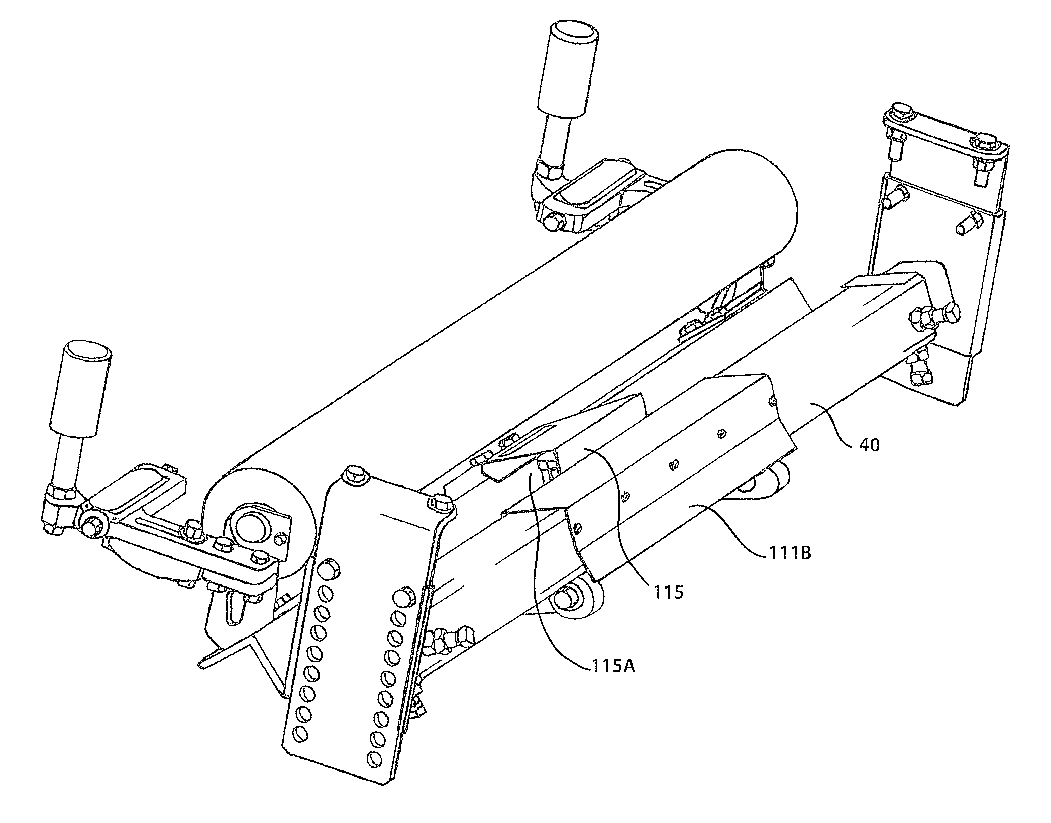
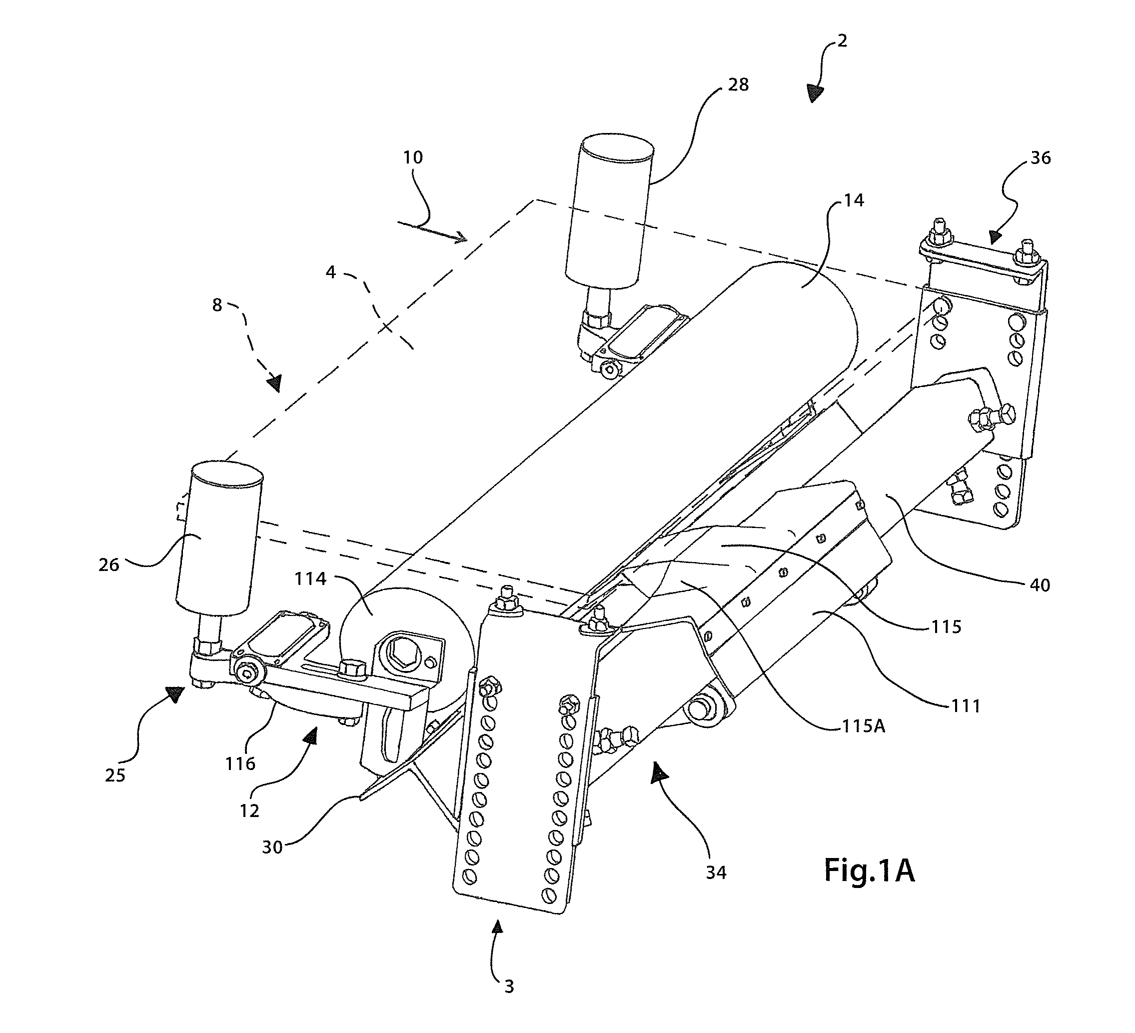
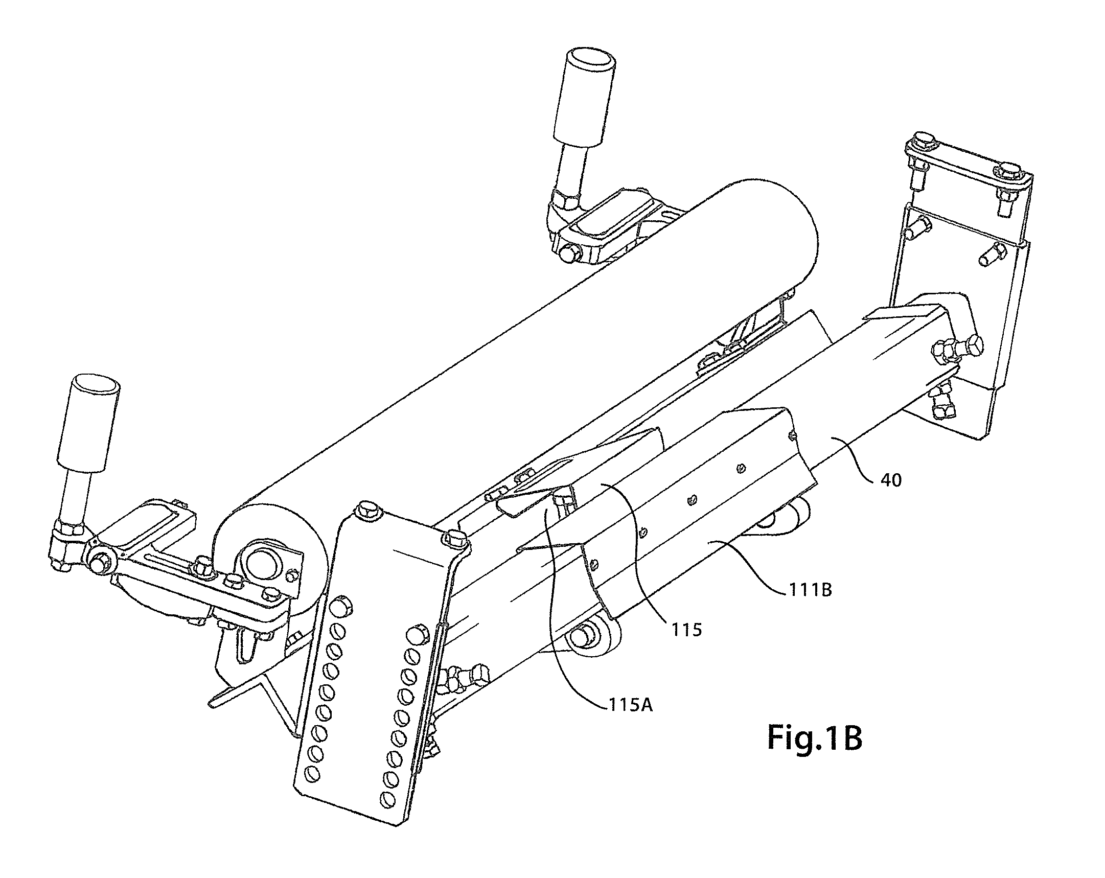
[0034]As illustrated in FIGS. 1A-4, a conveyor belt tracking apparatus 2 is well adapted to be utilized with a return run of an endless conveyor belt system (not shown) and is shown positioned under a conveyor belt 4 thereof to track the belt 4 along a generally longitudinal belt travel path, the center of which is indicated at broken line 6 in FIG. 2. To this end, the present conveyor belt tracking apparatus 2 will be described with respect to the return run 8 of an endless conveyor belt 4; however, it will recognized that the principles described herein for the conveyor belt training apparatus 2 can be adapted for use at other locations along the conveyor belt system including beneath the top run of the belt 4. Accordingly, the terminology relating to the orientation of the various components and portions thereof of the belt training apparatus 2 will be in reference to the return run 8 as it passes over the conveyor belt tracking apparatus 2 in a generally longitudinal downstream ...


PUM


Abstract

A conveyor belt tracking apparatus is provided for correcting the travel path of a laterally mistracking conveyor belt. In one form, an elongate tracking roller is rotatably mounted at end portions thereof to a pivotal support frame and extends across and below the belt. The pivotal support frame is mounted to a downstream pivot member so that belt mistracking toward one end portion of the tracking roller causes the one end portion to shift downstream and laterally outwardly to urge the belt toward the correct travel path. In one approach a downstream pivot connection between the pivot member and pivotal support frame is inclined upstream so that the end portion also shifts upwardly as it shifts downstream to urge the mistracking belt edge toward the correct travel path.

Description

CROSS REFERENCE TO RELATED APPLICATIONS[0001]This application claims benefit under 35 U.S.C. 119 (e) to U.S. Provisional Application No. 61 / 333,178 entitled “Method and Apparatus for Tracking Conveyor Belts” filed May 10, 2010, the contents of which are incorporated herein by reference in its entirety.FIELD OF THE INVENTION[0002]The invention relates to conveyor belt tracking apparatuses and methods for tracking conveyor belts.BACKGROUND[0003]Rollers for conveyor belts are arranged so that the conveyor belt travels thereover in a downstream belt travel direction and path. However, conveyor belts can tend to meander or mistrack toward one side or the other of the rollers such as due to uneven loads carried by the belt. Conveyor belt tracking devices have been developed that respond to belt mistracking to attempt to redirect the belt back to its correct travel path substantially central on the conveyor rollers.[0004]Conveyor belt trackers have commonly included a pivoting system that ...

Claims


Application Information

Patent Timeline
Patent Type & Authority Patents(United States)
IPC IPC(8): B65G15/08
CPCB65G39/16
Inventor DEVRIES, BRETT E.
Owner FLEXIBLE STEEL LACING
Why Eureka
Try Eureka