Eureka AIR delivers breakthrough ideas for toughest innovation challenges, trusted by R&D personnel around the world.

Power supply

a power supply and power adapter technology, applied in the field of power supplies, can solve the problems of occupying a large space, affecting the operation of conventional power supply systems, and affecting the use of devices, so as to facilitate wireless charging, facilitate use, and maintain the size of the power supply.

Active Publication Date: 2013-10-15
PHILIPS IP VENTURES BV
View PDF22 Cites 53 Cited by
  • Summary
  • Abstract
  • Description
  • Claims
  • Application Information

AI Technical Summary

Benefits of technology

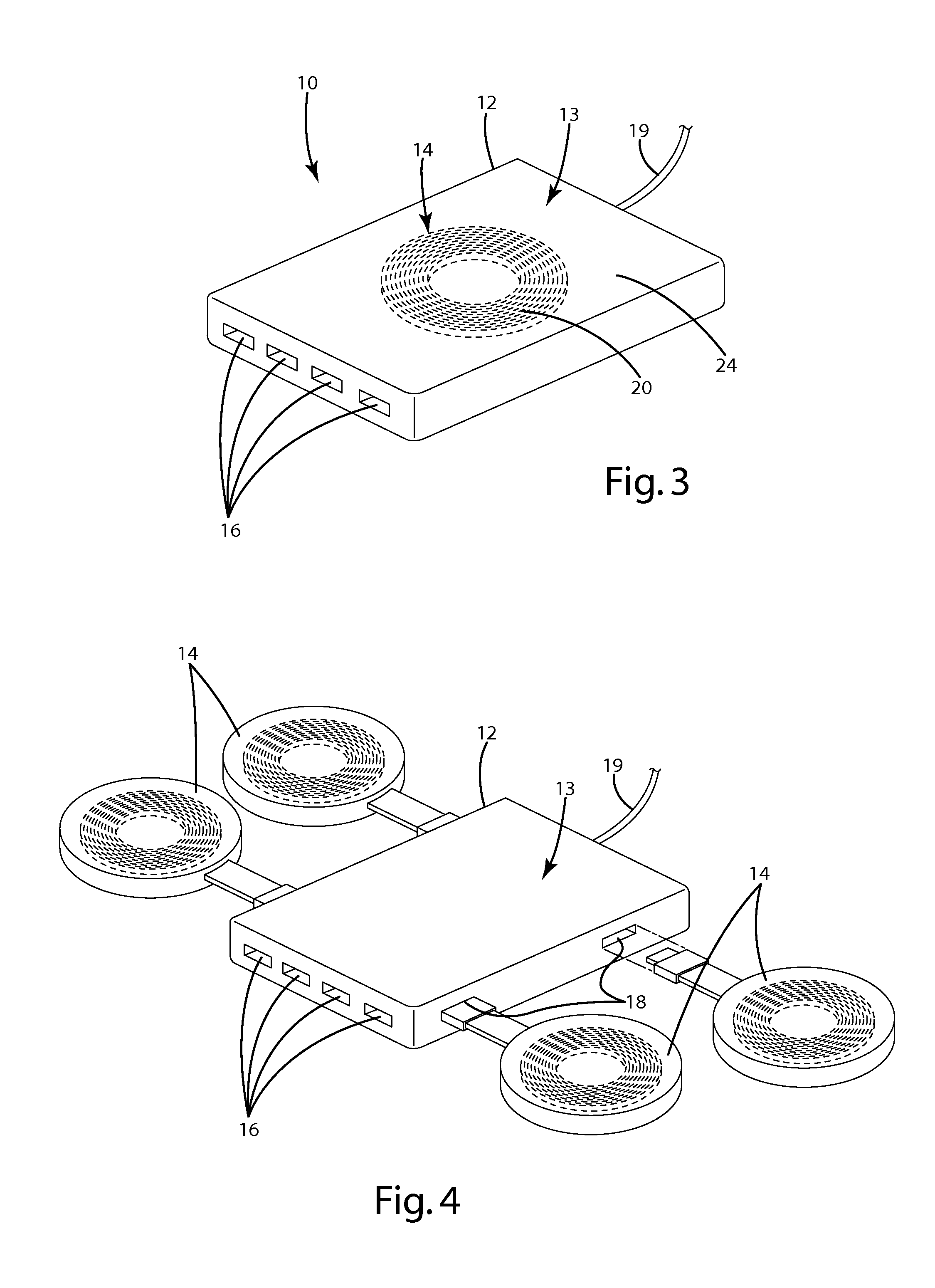
[0008]In a second aspect, the present invention provides a universal wireless power supply having a plurality of wireless power transmitters powered by a single power adapter. In one embodiment, the power adapter includes a plurality of integrated power transmitters and is configured to provide freedom of movement of the power transmitters. In one embodiment, the power transmitters may be connected to the power adapter by flexible connectors that permit the assembly to be folded up to reduce space. The flexible connectors may also provide the power transmitters with some degree of positional freedom.
[0011]In the first aspect, the present invention provides a universal power supply that is capable of supplying power to both wired and wireless electronic devices. In this aspect, the present invention provides a convenient, easy to use power supply that can be used for a wide variety of devices, thereby eliminating the need to carry multiple power supplies even when a user would like to power both wired and wireless devices. In a second aspect, the present invention provides a wireless power supply that is adaptable to different applications. In those embodiments with movable power supply sections, the power supply can be configured for easy storage and reconfigured to provide convenient wireless charging for devices of various types. In those embodiments with removable power supply transmitters, the size of the power supply can be kept to a minimum by adding only those power supply transmitters needed. The wireless power supply also adds the additional benefit of allowing inherent intrinsic safety. This element allows for high voltage within the power supply to be used with an inherent intrinsic safety. Power supply grounding and insulation can be more simple and cost effective that traditional power supplies. This also increases the safety and reliability of such power supplies. These power supplies can also include the an ultra low power option for minimum standby, such as the system described in U.S. Patent Publication 2010 / 0084918, filed on Oct. 2, 2009 entitled Power System, which is herein incorporated by reference in its entirety.

Problems solved by technology

Although a variety of standards have been developed for providing wireless communication with electronic devices, many of these devices continue to be plagued by the need for a power supply that is connected to the electronic device by a cord.
Power adapters (often referred to as “bricks”) are relatively heavy and occupy a large amount of space.
Conventional power supply systems suffer from a variety of disadvantages.
For example, the power supply with adapter and associated cords is a burden to use, store and carry around as needed.
In use, cords create an unsightly and often unmanageable mess.
Further, when connected, cords impede device mobility.
This only compounds the problem.
Efforts to provide a universal power solution are complicated by a variety of practical difficulties.
One of these difficulties arises because different portable electronic devices have different power requirements.
The introduction of wireless power solutions has in one respect made power management across multiple devices more complicated—at least in the short term.

Method used


Image

  • Power supply
  • Power supply
  • Power supply

Examples


Embodiment Construction

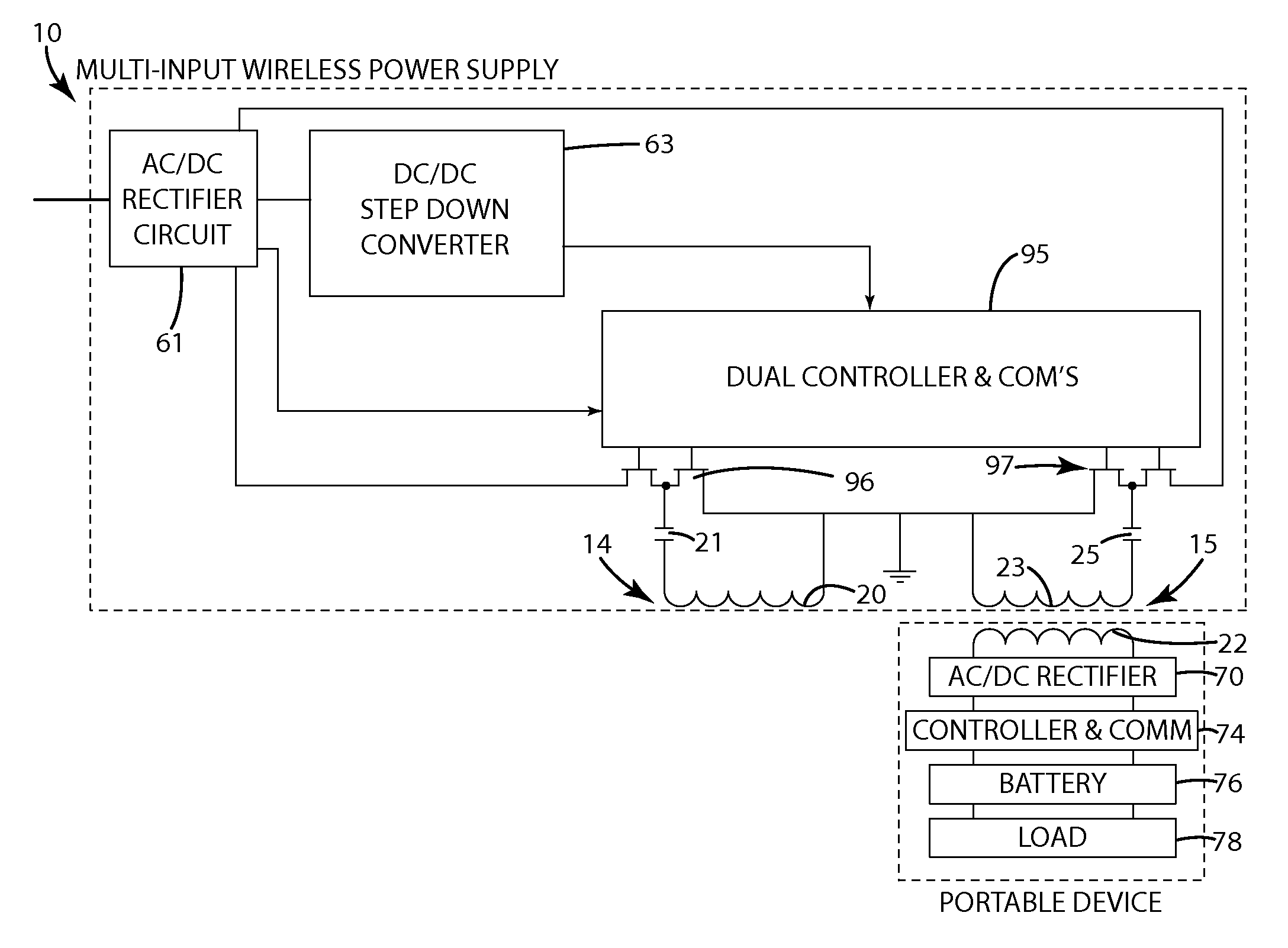
[0046]A power supply in accordance with an embodiment of one aspect of the present invention is shown in FIG. 3. The power supply 10 generally includes a power adapter 13 with a wireless power transmitter 14 to provide power to wireless electronic devices D and a plurality of power outlet ports 16 to provide power to wired electronic devices WD. The power adapter 13 includes the electronics required to convert AC mains power into the power required by the electronic devices. The wireless power transmitter 14 may be integrated into the power adapter 13 or may be attached to the power adapter 13 via a port 18 (shown in FIG. 4). In use, a user can attach a wired device WD to the power supply 10 using a conventional cord C inserted into the appropriate power outlet port 16. The wired device WD may use the power for operation and / or for charging an internal battery. Multiple wired devices WD can be connected to the power supply 10 using separate cords C inserted into different power outl...


PUM

PropertyMeasurementUnit
input voltageaaaaaaaaaa
voltageaaaaaaaaaa
diameteraaaaaaaaaa

Abstract

In one aspect, the present invention provides a universal power supply for wired and wireless electronic devices. In a second aspect, the present invention provides a universal power supply that is reconfigurable to provide a wide range of power supply options.

Description

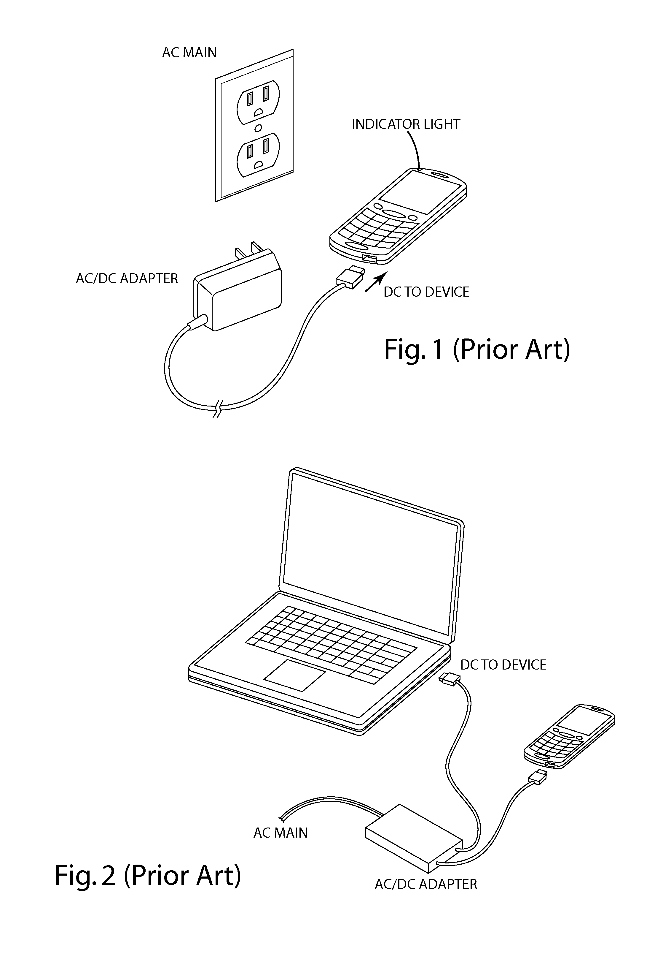
BACKGROUND OF THE INVENTION[0001]The present invention relates to power supplies and more particularly to power supplies capable of supplying power to a variety of alternative devices.[0002]There continues to be dramatic growth in the use of portable electronic devices, such as laptops, personal digital assistants, cellular phones, smart phones and portable media players. Although a variety of standards have been developed for providing wireless communication with electronic devices, many of these devices continue to be plagued by the need for a power supply that is connected to the electronic device by a cord. Typically, each power supply includes a power adapter for converting AC mains power into the DC power required by the device along with cords for connecting the input of the adapter to a wall outlet and the output of the adapter to the electronic device. In some cases, a plug extends from the adapter so that the adapter plugs directly into a wall outlet and only a single cord...

Claims


Application Information

Patent Timeline
Patent Type & Authority Patents(United States)
IPC IPC(8): H01F27/42H01F37/00H01F38/00
CPCH02J5/005H02J7/0027H02J7/0042H02J7/0044H02J7/025H02J50/12H02J50/402H02J7/0013H02J50/90H02J50/40
Inventor BAARMAN, DAVID W.STONER, JR., WILLIAM T.NGUYEN, HAI D.
Owner PHILIPS IP VENTURES BV
Why Eureka
Eureka Blog
Learn More