
Instrument cluster and methods thereof

a technology of instruments and clusters, applied in instruments, lighting and heating apparatus, machines/engines, etc., can solve problems such as poor aesthetics, user disturbance, and difficulty in assembling the pcb assembly into

Active Publication Date: 2013-10-22
PRICOL LTD
View PDF10 Cites 7 Cited by
  • Summary
  • Abstract
  • Description
  • Claims
  • Application Information

AI Technical Summary

Benefits of technology

The invention is an instrument cluster that includes a PCB assembly with a drive source, a light guide, and a reflector. The cluster has a bottom and top pointer, each connected to the drive source, and a case assembly for supporting the PCB assembly. The method of operation involves rotating the drive source shaft and illuminating the pointer with the light source on the PCB. The technical effects are improved visibility and operability of the instrument cluster.

Problems solved by technology

Further the shadow may lead to poor aesthetic look and may also disturb the user.
The limitations in the existing method of pointer indication are;The product construction requires at least two PCB (Top and Bottom), wherein the bottom PCB is for holding stepper motor (7) and the top PCB is for light source assembly (Light Emitting Diode),New connector is also required to connect said two PCB's.Geometry of the pointer leads to difficulty in assembling the PCB assembly into the instrument cluster,An additional frame is used for holding the two each other indication panel, indication plate and the light source,The product construction requires more spaces for accommodating the both electronics and mechanical components.
This is not suitable for very compact design of instrument clusters,Additional component No. 3 is used for pointer illumination,Additional component No. 4 is used for holding the PCB, andGeometry of the pointer may produce warp.
The aforesaid disadvantages of the related art in-turn increase the cost and require more space of the instrument cluster.

Method used


Image

  • Instrument cluster and methods thereof
  • Instrument cluster and methods thereof
  • Instrument cluster and methods thereof

Examples


Embodiment Construction

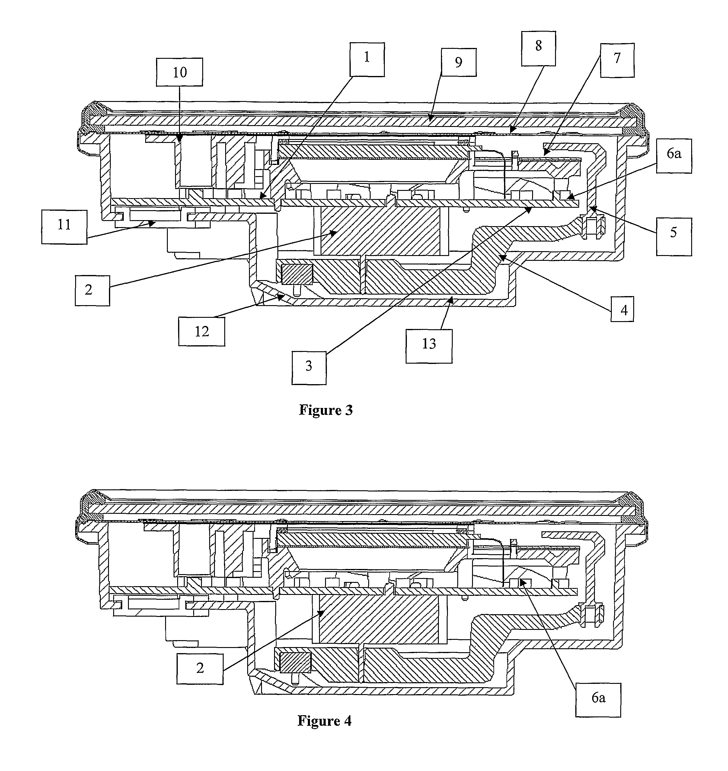
[0033]The present invention is in relation to an instrument cluster comprising; a Printed Circuit Board (PCB) assembly comprising a drive source connected to the PCB (1) and is mounted in such a way that, stem of the drive source faces towards bottom side of the PCB (1) and pointer is pressed from the bottom side of the PCB (1) for driving a top pointer, a light guide (6) mounted above the PCB (1) comprising a light source and a reflector (3) mounted above the light source, a pointer characterized into a bottom pointer (4) and a top pointer (5), wherein said bottom pointer (4) is connected to the drive source and said top pointer (5) is connected to the bottom pointer (4), and case assembly (13) mounted below the PCB assembly for supporting the PCB assembly.

[0034]In still another embodiment of the present invention the PCB assembly is having predetermined geometric shape, preferably flat.

[0035]In yet another embodiment of the present invention the drive source is preferably a steppe...


PUM


Abstract

The present invention relates to an instrument cluster, more particularly relates to an improved instrument cluster having a Printed Circuit Board [PCB (1)] which holds the pointer drive source and an illumination source of pointer. The instant invention also provides for a method of operating the instrument cluster and method of assembling the instrument cluster.

Description

CROSS REFERENCE TO RELATED APPLICATION(S)[0001]This application is a 35 USC §371 National Stage application of International Application No. PCT / IN2009 / 000012 filed Jan. 5, 2009, now pending; which claims the benefit under 35 USC §119(a) to India Patent Application No. 00032 / CHE / 2008 filed Jan. 3, 2008. The disclosure of each of the prior applications is considered part of and is incorporated by reference in the disclosure of this application.FIELD OF THE INVENTION[0002]The present invention relates to an instrument cluster, more particularly relates to an improved instrument cluster having a Printed Circuit Board (PCB) which holds the pointer drive source and an illumination source of pointer. The instrument finds its potential application in automobile industry.BACKGROUND OF THE INVENTION AND PRIOR ARTS[0003]The instrument clusters mainly comprised of pointers to indicate the speed or RPM of an engine and fuel level on an index plate / dial. Normally the pointer moves with respect t...

Claims


Application Information

Patent Timeline
Patent Type & Authority Patents(United States)
IPC IPC(8): G01D11/28
CPCB60R16/0239G12B11/04B60K37/02B60K2350/307B60K2350/302B60K2360/336B60K2360/48B60K2360/42B60K2360/46B60K2360/6985B60K2360/96B60K37/20B60K35/60
Inventor MANIVANNAN, MANIKESIKANAGARAJ, RANGAPPANKANAKARAJU, KRISHNASAMY
Owner PRICOL LTD
Learn More