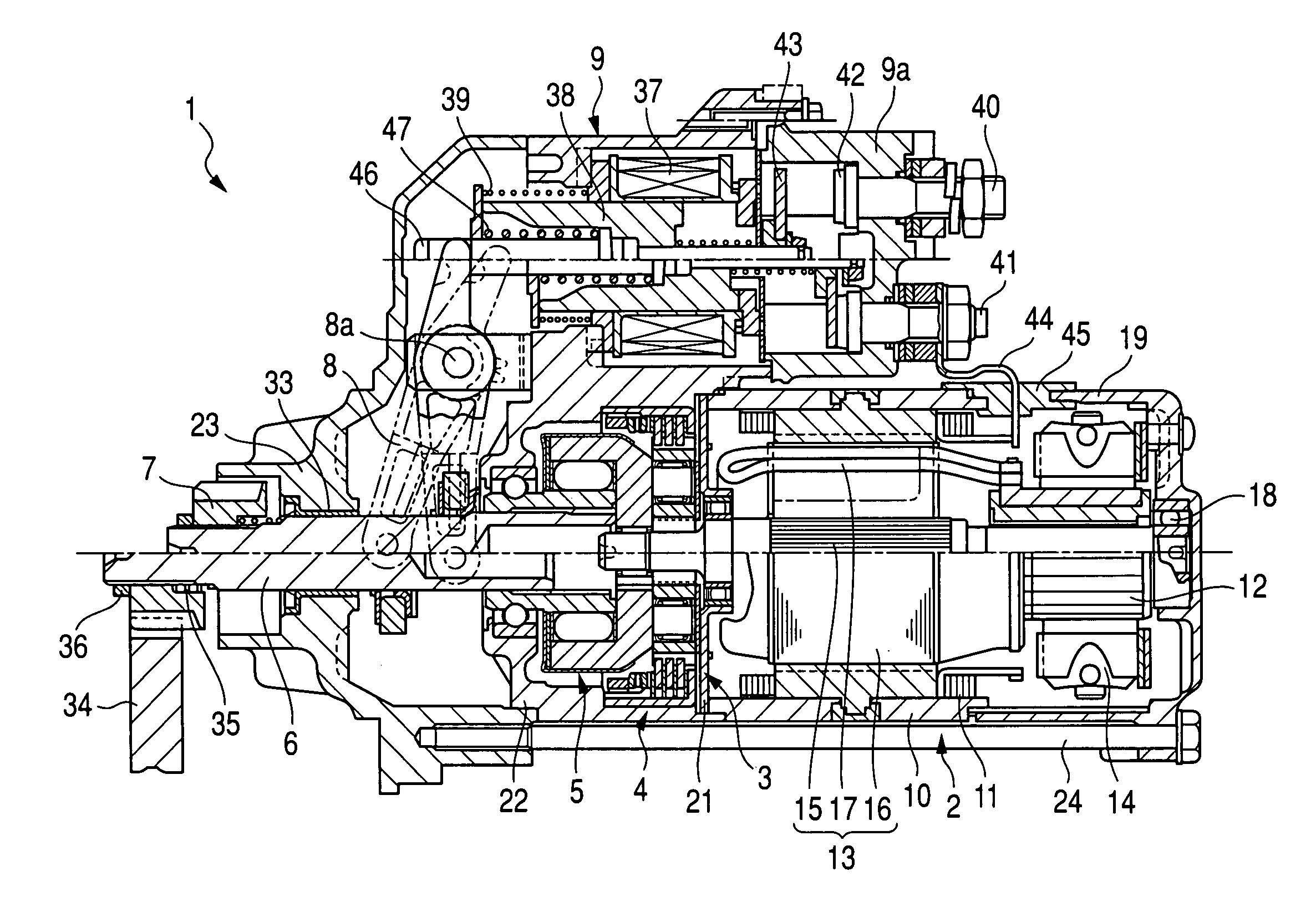
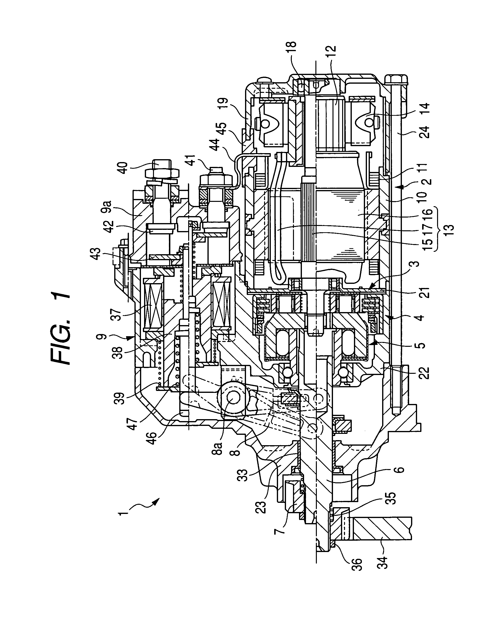
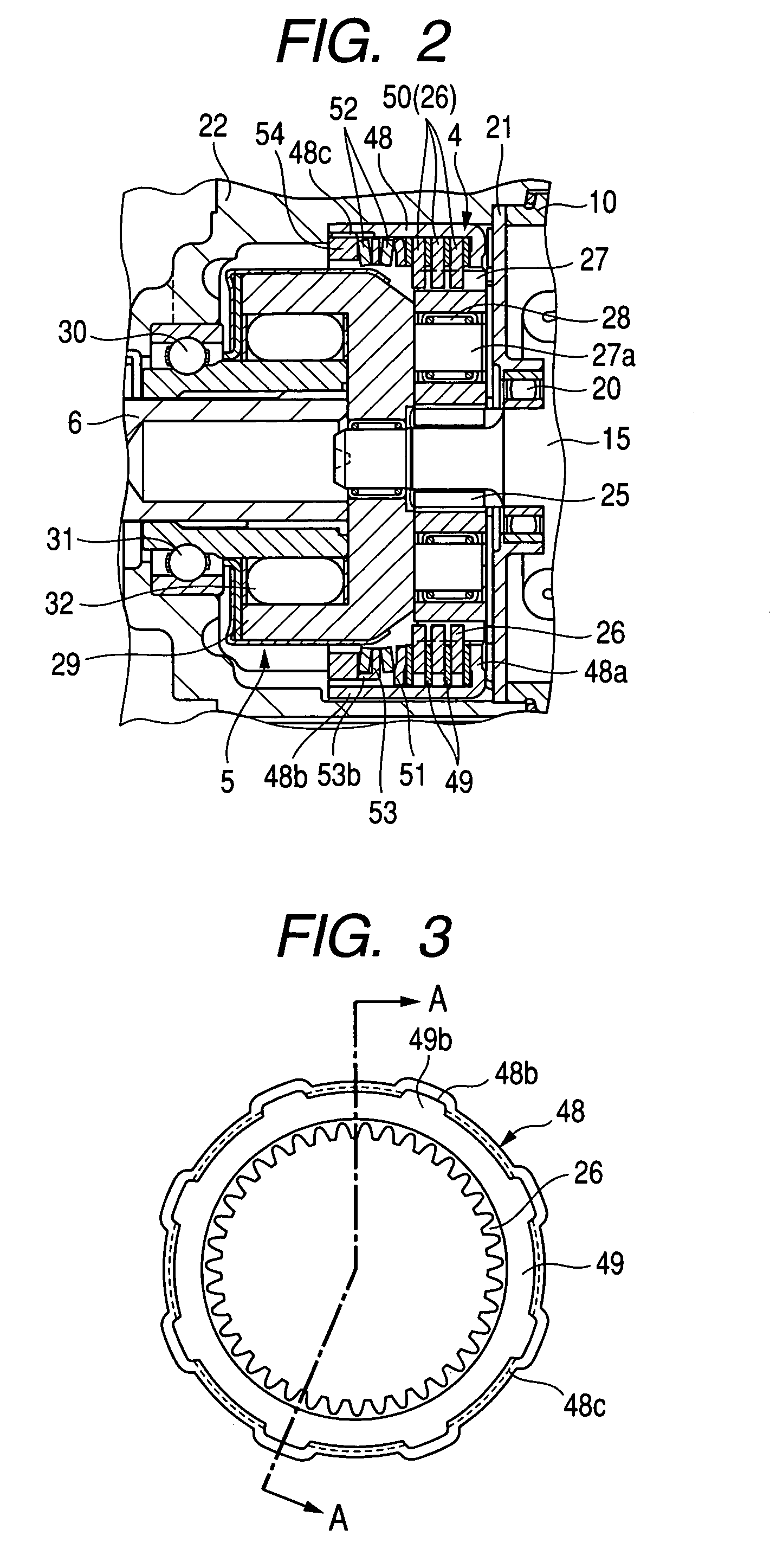
Starter equipped with planetary speed reducer and shock absorber
a technology of planetary speed reducer and shock absorber, which is applied in the direction of engine starters, electric motor starters, machines/engines, etc., can solve the problems of reducing the slip torque of internal gears, lack of elastic pressure applied to lack of tightening the nut to exert pressure on the stack of stationary and rotary discs, so as to minimize the bias of load and avoid undesirable plate movement. , the effect of reducing
- Summary
- Abstract
- Description
- Claims
- Application Information
AI Technical Summary
Benefits of technology
Problems solved by technology
Method used
Image
Examples
second embodiment
[0080]The starter 1 of the second embodiment will be described below.
[0081]The shock absorber 4 of the first embodiment, as described above, restrains one of the disc springs 52 which is located closer to the nut 54 from moving in the radius direction thereof. The shock absorber 4 of the second embodiment is designed to restrains both the disc springs 52 from moving in the radius direction.
[0082]Specifically, the protrusions 53a of the washer 53, as illustrated in FIG. 7, are bent in a direction opposite that in which the claws 53b extend, that is, toward the internal gear 26 to form, as illustrated in FIG. 9, claws 53c in addition to the claws 53b. In other words, the protrusions 53a of the washer 53 are broken down into a first group of the claws 53b and a second group of the claws 53c. The first group of the claws 53b extend in one of opposite axial directions of the washer 53 (i.e., opposite axial directions of the output shaft 6, while the second group of the claws 53c extend i...
first embodiment
[0084]The washer 53 is, like in the first embodiment, held from rotating, thereby restraining the movement of the washer 52 arising from tightening of the nut 54. This ensures the stability in exerting the pressure or load on the washer 53 to set the slip torque accurately.
third embodiment
[0085]The starter 1 of the third embodiment will be described below.
[0086]The shock absorber 4 of the second and third embodiments is designed to hold the disc spring(s) 52 from moving in the radius direction thereof using the claws 53b and / or 53c. The shock absorber 4 of this embodiment is designed to have annular grooves 53d, as illustrated in FIGS. 11(a), 11(b), and 11(c), formed in major surfaces of the washer 53 facing the disc springs 52. Specifically, the annular grooves 53d are formed by, for example, a press coaxially in the opposed surfaces of the washer 53. The disc springs 52, as clearly illustrated in FIG. 11(c), have inner circumferential corners or edges which face each other in the axial direction of the washer 53 and are fit in the annular grooves 53d to restrain the disc springs 52 from moving in the radius direction thereof.
[0087]The engagement of the circumferential edges of the disc springs 52 with the annular grooves 53d of the washer 53, like in the first and ...
PUM
 Abstract
Description
Claims
Application Information
 - R&D
- Intellectual Property
- Life Sciences
- Materials
- Tech Scout
- Unparalleled Data Quality
- Higher Quality Content
- 60% Fewer Hallucinations
Browse by: Latest US Patents, China's latest patents, Technical Efficacy Thesaurus, Application Domain, Technology Topic, Popular Technical Reports.
© 2025 PatSnap. All rights reserved.Legal|Privacy policy|Modern Slavery Act Transparency Statement|Sitemap|About US| Contact US: help@patsnap.com


