Fiber-optic connector

a fiber-optic connector and fiber-optic technology, applied in the field of optical connectors, can solve the problems of increased optical fiber connection loss, unsuitable method, undesirable contamination, etc., and achieve the effect of reducing the loss of fresnel reflection of the fiber-optic connector

Inactive Publication Date: 2013-10-29
BAE SYST INFORMATION & ELECTRONICS SYST INTERGRATION INC
View PDF13 Cites 2 Cited by
  • Summary
  • Abstract
  • Description
  • Claims
  • Application Information

AI Technical Summary

Benefits of technology

[0011]In accordance with a preferred embodiment of the present invention, a fiber-optic connector includes a top plate having a window of similar refractive index and transmission index as the material of an optic fiber to be contained within the fiber-optic connector. The fiber-optic connector also includes a ferrule connected to the top plate via multiple spring-loaded screws. The ferrule includes an interface and an insert. The insert is capable of firmly gripping an optical fiber. In order to reduce Fresnel reflection losses of the fiber-optic connector, the window is pre-coated with an anti-reflective surface on the side opposite an optic fiber to be contained within the fiber-optic connector.

Problems solved by technology

As a result, Fresnel reflection increases at the end face of the optical fiber, and leads to an increase in connection loss of the optical fiber.
However, this method is not suitable when the external optical fiber (such as holey fiber or soft glasses) is very sensitive or when the connection work is conducted at the setting site of the optical fiber because of the necessity of a polishing device and high labor cost.
However, this method has the following problems.
Since the refractive index matching agent is generally formed of a silicone or paraffin agent in liquid or grease state, it can cause undesirable contamination (to holey fibers or high-power fibers).
Unfortunately, some optical fiber materials, such as mid-infrared sensitive glasses, in high-power applications may be unsuitable for this method.

Method used


Image

  • Fiber-optic connector
  • Fiber-optic connector

Examples


Embodiment Construction

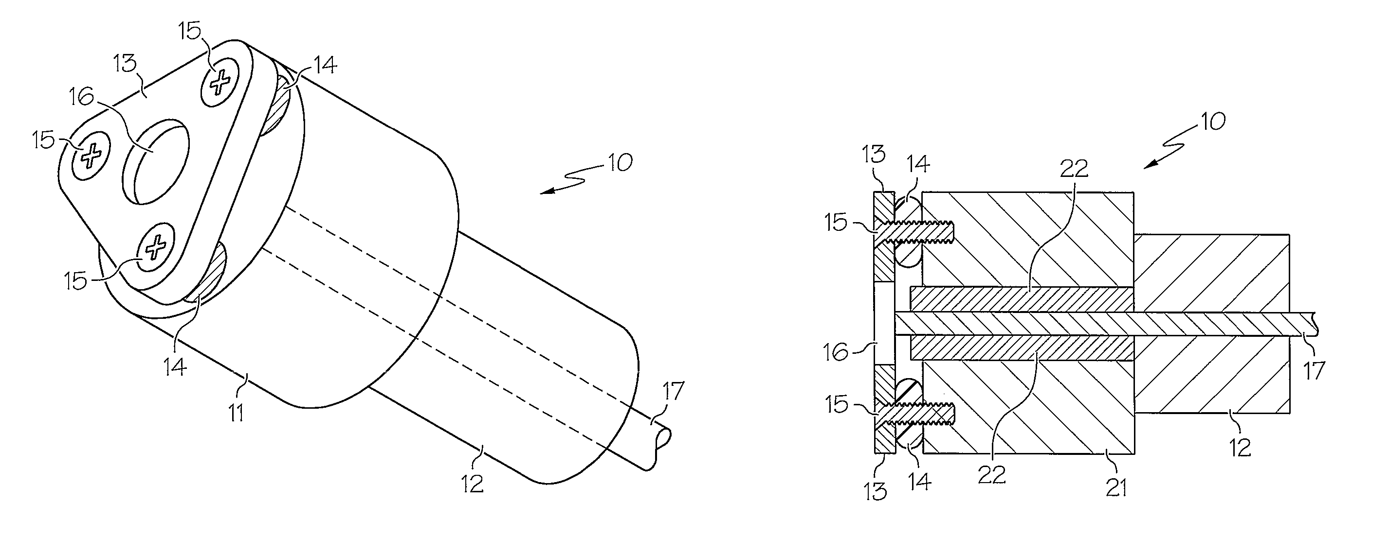
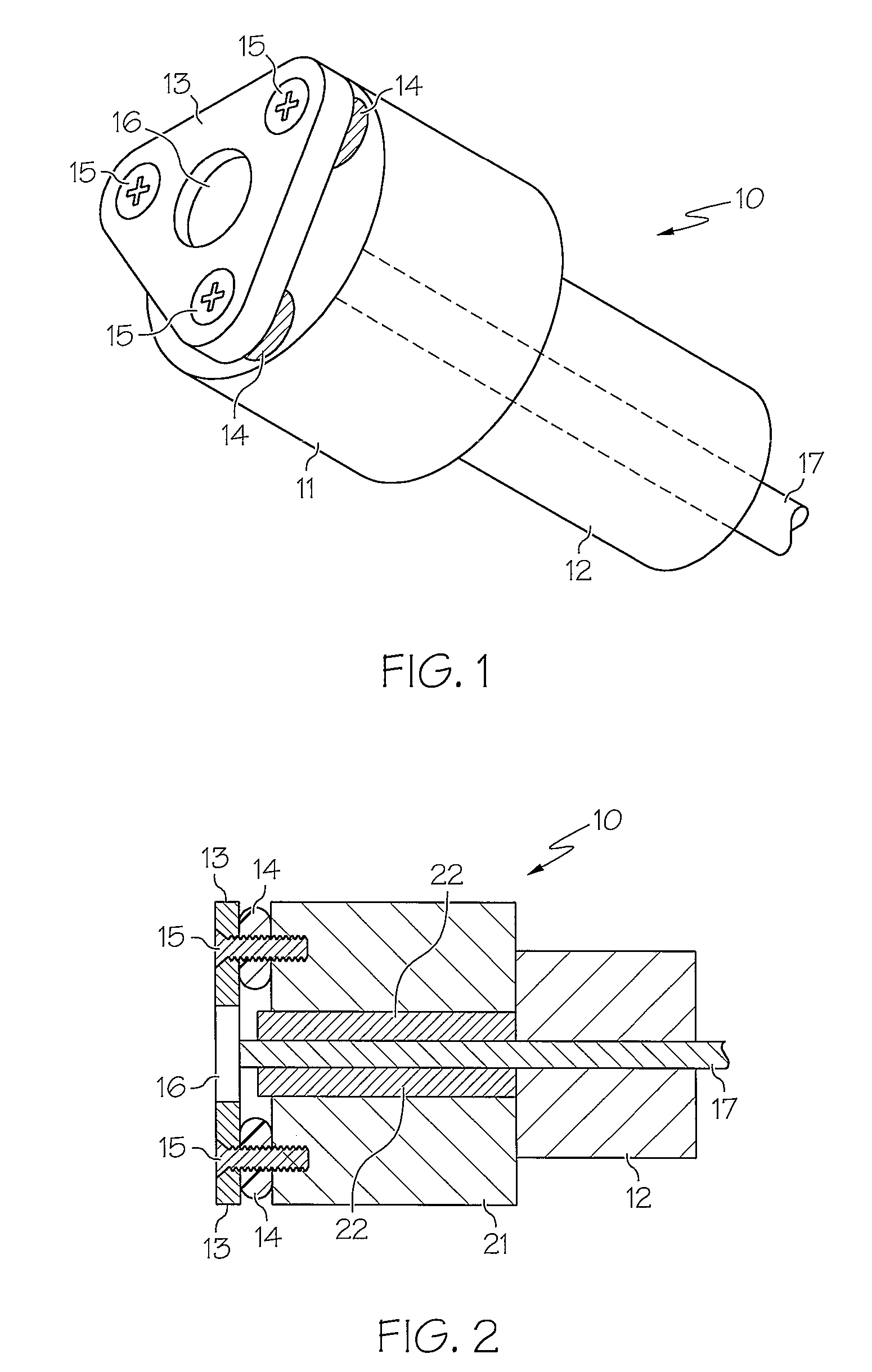
[0016]Referring now to the drawings and in particular to FIG. 1, there is illustrated an isometric view of a fiber-optic connector, in accordance with a preferred embodiment of the present invention. As shown, a fiber-optic connector 10 includes a ferrule 11 and a housing 12. In addition, fiber-optic connector 10 also includes a top plate 13 and multiple O-rings 14. Ferrule 11 is a cylindrical member with a center hole for receiving an optical fiber. Top plate 13 and O-rings 14 are preferably secured to a front end of ferrule 11 via multiple screws 15. Housing 12 is connected to a back end of ferrule 11.

[0017]O-rings 14 act as shock absorbers between top plate 13 and ferrule 11. O-rings 14 can be substituted by RTV silicone gaskets or springs. Although top plate 13 is shown to be in a triangular shape having three screw holes at each apex of the triangle, it is understood by those skilled in the art that top plate 13 can be of any shape with any number of screw holes.

[0018]For the p...


PUM


Abstract

A fiber-optic connector for connecting an optical fiber to other optical assemblies is disclosed. The fiber-optic connector includes a top plate having a window of similar refractive index and transmission index as the material of an optic fiber to be contained within the fiber-optic connector. The fiber-optic connector also includes a ferrule connected to the top plate via multiple spring-loaded screws. The ferrule includes an interface and an insert. The insert is capable of firmly gripping an optical fiber. In order to reduce Fresnel reflection losses of the fiber-optic connector, the window is pre-coated with an anti-reflective surface on the side opposite an optic fiber to be contained within the fiber-optic connector.

Description

STATEMENT OF GOVERNMENT INTEREST[0001]The present invention was made with United States Government support under contract number N00173-05-C-6020 awarded by the U.S. Naval Research Lab. The United States Government has certain rights in the present invention.BACKGROUND OF THE INVENTION[0002]1. Technical Field[0003]The present invention relates to optical connectors in general, and in particular to a fiber-optic connector having an embedded window for connecting an optical fiber to other optical assemblies.[0004]2. Description of Related Art[0005]A fiber-optic connector is typically utilized to connect an optical fiber to other optical assemblies. A fiber-optic connector commonly includes a ferrule in which an internal optical fiber is housed.[0006]The profile of the end face of an optical fiber can significantly affect its connection characteristics. For example, when an angle (i.e., an angle to the optical fiber axis) of the end face of an optical fiber deviates from a right angle ...

Claims


Application Information

Patent Timeline
Patent Type & Authority Patents(United States)
IPC IPC(8): G02B6/38
CPCG02B6/3818G02B6/3861G02B6/3855G02B6/3849
Inventor OWEN, III, JOSEPH MCLELLANKELLY, DAVID PAUL
Owner BAE SYST INFORMATION & ELECTRONICS SYST INTERGRATION INC
Why Eureka
Try Eureka