Plasma film forming apparatus

a technology of plasma film and forming apparatus, which is applied in the direction of coating, chemical vapor deposition coating, coating process, etc., can solve the problems of high equipment cost, high cost of high-vacuum pump per se, and high cost of chamber, and achieve the effect of efficient use of film raw materials

Inactive Publication Date: 2013-11-05
HONDA MOTOR CO LTD
View PDF61 Cites 282 Cited by
  • Summary
  • Abstract
  • Description
  • Claims
  • Application Information

AI Technical Summary

Benefits of technology

[0013]A general object of the present invention is to provide a plasma film forming apparatus capable of efficiently using a film raw material.
[0014]A principal object of the present invention is to provide a plasma film forming apparatus capable of material cost reduction and resource saving.
[0015]Another object of the present invention is to provide a plasma film forming apparatus capable of forming a film without limitations on the size and shape of a substrate.

Problems solved by technology

However, in this case, the high-vacuum pump per se is expensive.
In addition, the chamber has to be pressure resistant, so that also the chamber becomes expensive.
Therefore, the conventional plasma film forming method is clearly disadvantageous in high equipment cost.
Furthermore, the film formation subject is limited to a substrate that can be contained in a chamber.
However, the apparatus is disadvantageous in that an impurity such as air is mixed in a generated plasma discharge gas, whereby the resultant film contains a large amount of the impurity.
Therefore, the film has low quality and hardly exhibits the desired function.
Thus, in the technology, the raw material gas is used in an amount greatly exceeding the minimum amount required to form the film, resulting in high material cost.

Method used


Image

  • Plasma film forming apparatus
  • Plasma film forming apparatus
  • Plasma film forming apparatus

Examples


example

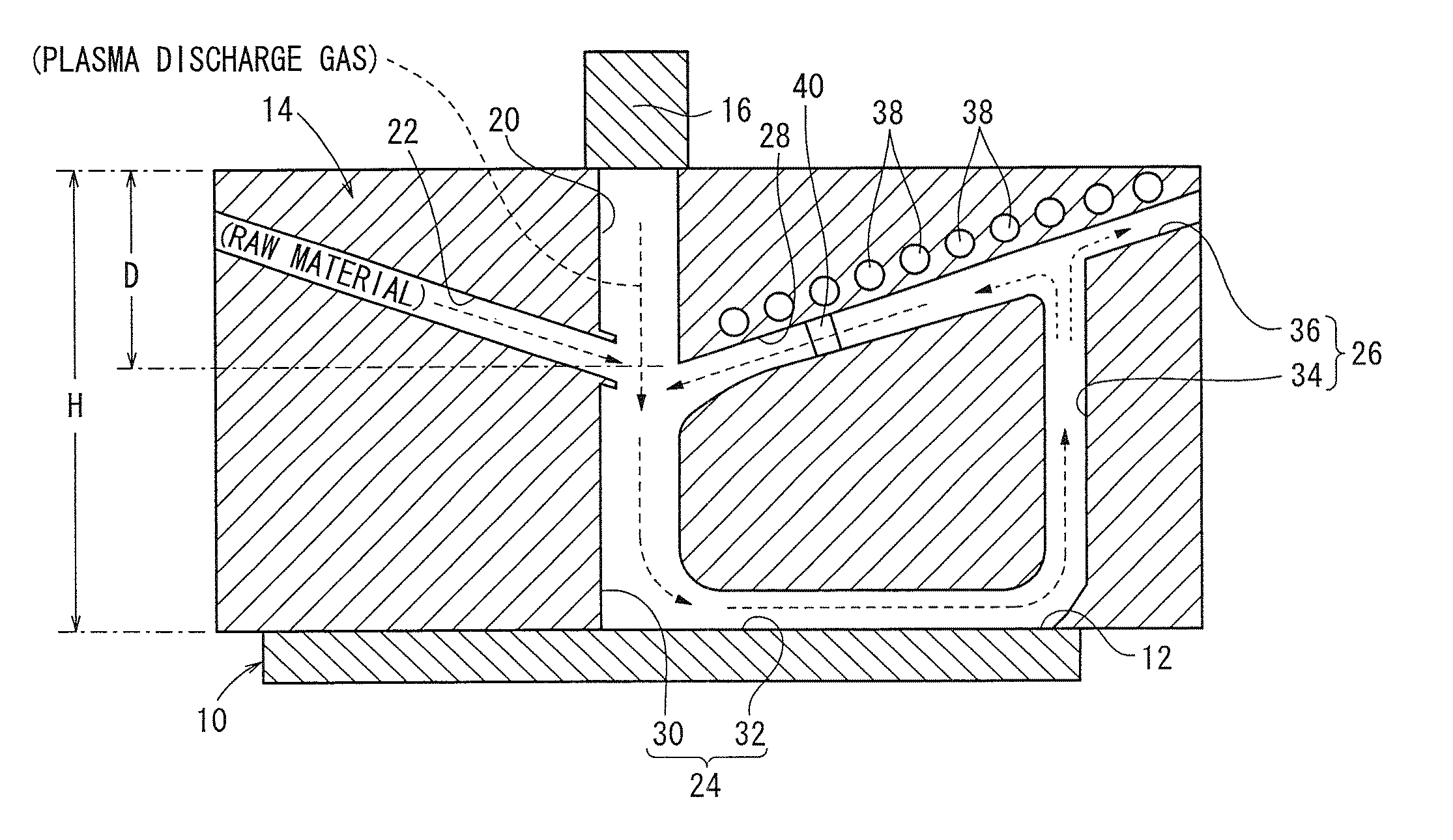
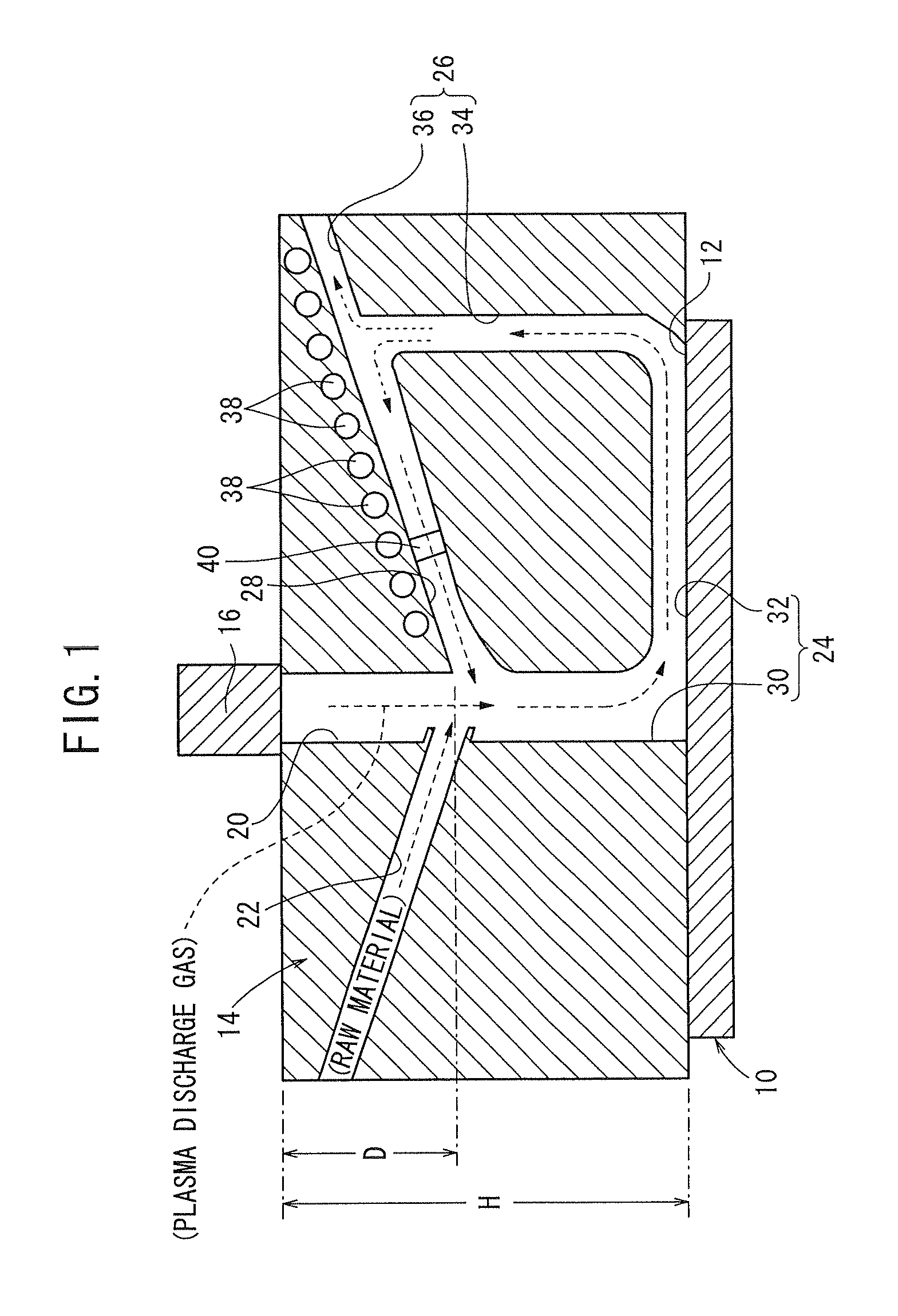
[0075]Films were formed by using the plasma film forming apparatus containing the flow control jig 14 having a height H of 10 mm and a distance D of 1 mm shown in FIG. 1. The substrate 10 and the raw material were a polycarbonate substrate and hexamethyldisiloxane, respectively. The plasma discharge gas was obtained from an He / O2 mixed gas having an He / O2 volume ratio of 98 / 2 by a plasma generation apparatus manufactured by Plasma Concept Tokyo, Inc., and was ejected from the plasma nozzle 16 at a flow rate of 100 cm / second.

[0076]Meanwhile, a cooling water was circulated in the cooling tubes 38, and a cold trap was placed in the opening of the outward emission passage 36. The cold trap acted to cool the plasma discharge gas discharged from the opening of the outward emission passage 36, whereby the raw material contained therein was condensed (or solidified) and collected.

[0077]In the case of not using the filter 40 in the recovery path 28, the film formation rate was 1.2 μm / minute,...


PUM

PropertyMeasurementUnit
sizeaaaaaaaaaa
distanceaaaaaaaaaa
heightaaaaaaaaaa

Abstract

The present invention relates to a plasma film forming apparatus. In the plasma film forming apparatus, a flow control jig is disposed between a plasma nozzle and a film formation region of a substrate. The flow control jig has a plasma supply path, a raw material supply path, a film formation joined path formed by combining the plasma supply path and the raw material supply path, an exhaust path for discharging a plasma discharge gas and an unreacted raw material transported from the film formation region, and a recovery path for returning the unreacted raw material in the exhaust path to the plasma supply path.

Description

CROSS-REFERENCE TO RELATED APPLICATION[0001]This application is based upon and claims the benefit of priority from Japanese Patent Application No. 2010-005021 filed on Jan. 13, 2010, of which the contents are incorporated herein by reference.BACKGROUND OF THE INVENTION[0002]1. Field of the Invention[0003]The present invention relates to a plasma film forming apparatus for activating a raw material for a film, thereby depositing the material to form a film on a surface of a substrate.[0004]2. Description of the Related Art[0005]Films such as protective films and functional films have been widely used on a surface of a substrate composed of a plastic, metal, or ceramic. One known method for forming such films (i.e. film formation) is a plasma film forming method using a plasma.[0006]The plasma film forming method is generally carried out in a plasma film forming apparatus having a chamber equipped with a high-vacuum pump or the like. Thus, a substrate is placed in the chamber, the cha...

Claims


Application Information

Patent Timeline
Patent Type & Authority Patents(United States)
IPC IPC(8): C23C16/455C23C16/50C23F1/00H01L21/306C23C16/452C23C16/22C23C16/06
CPCC23C16/45512C23C16/45517C23C16/45563C23C16/45587C23C16/45593C23C16/50C23C16/52
Inventor YOROZUYA, SHUNICHI
Owner HONDA MOTOR CO LTD
Why Eureka
Try Eureka