Heterodyne polarimeter with a background subtraction system

a heterodyne polarimeter and subtraction system technology, applied in the direction of polarisation-affecting properties, optical radiation measurement, instruments, etc., can solve the problems of severe birth defects, high toxicities of other materials, and inability to always be possible, so as to improve the accuracy of the heterodyne polarimeter

Inactive Publication Date: 2013-11-05
MELLITOR
View PDF9 Cites 0 Cited by
  • Summary
  • Abstract
  • Description
  • Claims
  • Application Information

AI Technical Summary

Benefits of technology

[0012]It is an object of the present invention to improve the accuracy of a heterodyne polarimeter by employing an efficient background subtraction scheme.
[0050]It should also be understood by those skilled in the art that the signal-to-noise ratio (SNR) and sensitivity of the heterodyne polarimeter of the current invention can be considerably improved by substantially attenuating (with the aid, for example, of a neutral density attenuator) the intensity of the frequency-shifted second linearly polarized light beam with respect to the intensity of the linearly polarized reference and measurement beams. This relative attenuation, which can typically be by a factor of 10-104, reduces the basal amount of light incident on the detector and serves to reduce the shot noise and increase the relative contribution of the heterodyne signal.
[0052]This alternative setup comes at the cost of losing some laser power at the second non-polarizing beam splitter and introducing some differences between the reference and measurement beams, which might introduce additional sources of polarization noise. However, it enables the use of simpler optical elements instead of the more complex variable phase retarder.
[0053]The heterodyne polarimeter of the current invention can be realized by using independent optical components, such as cube beam splitters, calcite polarizers and coated glass lenses. Alternatively, it can be built by using integrated optical components based on an optical waveguiding platform, such as planar waveguides and optical fibers. The latter option opens the way for miniaturization of the polarimeter.
[0054]The heterodyne polarimeter in accordance with the present invention has several advantages: 1) the reference and measurement beams share a common path, making the polarimeter less susceptible to vibrations; 2) because only one laser source is used, laser phase noise and power fluctuations can be canceled; 3) the effect of low-frequency phase noise, generated by thermal effects, can be reduced by using the heterodyne signal of the reference beam; 4) any heterodyne signal at the expected frequency, which is generated by the reference beam, must result from background noise and can be subtracted from the heterodyne signal generated by the measurement beam, allowing for efficient filtering of the optical activity signal; 5) the measurement cell containing the optically active substance is traversed twice by the measurement beam enabling the doubling of the optical rotation signal; 6) the optical setup is simple and no bulky, power-consuming components like Faraday rotators are required. Moreover, once the ratio between the reference and measurement heterodyne signals at zero optical activity in the measurement cell is established and remains constant, there is no further need to measure reference (blank) samples.

Problems solved by technology

This difference can become crucial in the pharmaceutical industry, where in many cases only one enantiomer of a drug has the desired therapeutic activity while the other can be highly toxic.
For example, one enantiomer of the notorious medication Thalidomide had the intended sedative effect, while the other was extremely teratogenic and caused severe birth defects.
Nevertheless, this is not always possible, especially when the background signal rapidly changes or when a parallel, but different, optical setup is needed to measure the reference sample.
However, this polarimeter cannot distinguish between a heterodyne signal resulting from increased optical activity in the sample or a one resulting from increased depolarization by scattering along the optical path.
Any attempt in such a polarimeter to sample the laser beam by inserting a beam splitter into the optical train is likely to introduce polarization noise, which cannot be canceled.
Here too, no distinction can be made between the optical activity dependent signal and signals generated by background polarization noise, for example, due to increased depolarization caused by scattering in the cell holding the sample.
This polarimeter also is likely to be sensitive to mechanical phase noise in the optical setup responsible for the phase modulation.
Canceling this phase noise will necessitate the sampling of the beam before the measurement cell, introducing yet another source of polarization noise.

Method used


Image

  • Heterodyne polarimeter with a background subtraction system
  • Heterodyne polarimeter with a background subtraction system
  • Heterodyne polarimeter with a background subtraction system

Examples


Embodiment Construction

[0058]The invention will now be illustrated by detailed description of the following non-limiting embodiments of the polarimeter of the invention, with reference to the figures. In the following detailed description of the embodiments, reference is made to the accompanying drawings that form a part thereof, and in which are shown by way of illustration specific embodiments in which the invention may be practiced. It is understood that other embodiments may be utilized and structural changes may be made without departing from the scope of the present invention.

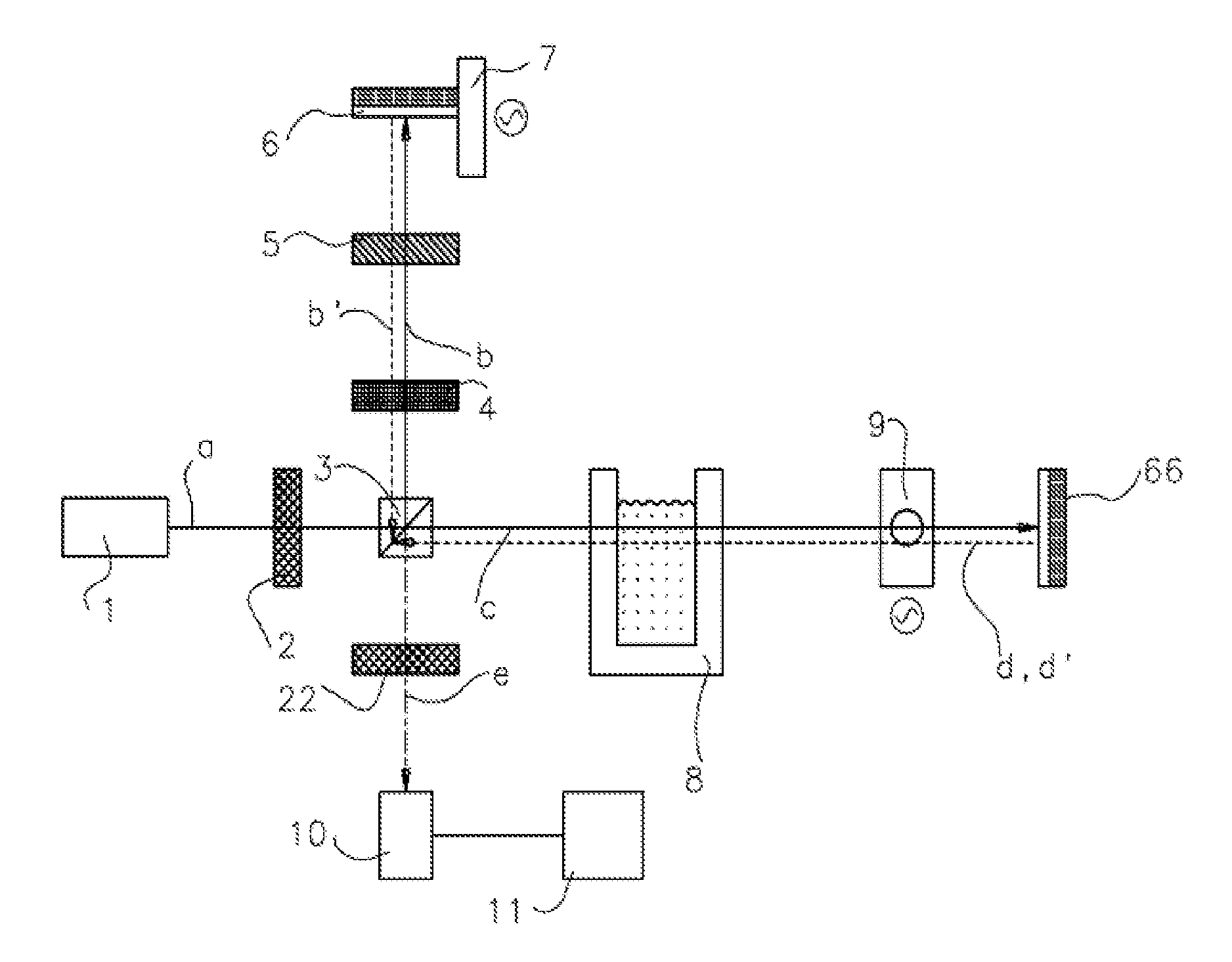
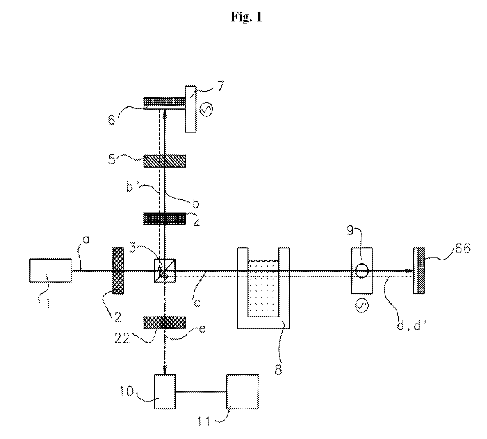
[0059]FIG. 1 shows a scheme of a device for the quantitative determination of optically active substances in a solution, conforming to a first exemplary embodiment. The device includes a laser source that emits coherent light. The wavelength of the emitted light can typically range from 400 nanometers to 900 nanometers.

[0060]The laser source 1 generates a first coherent light beam (a). The first light beam (a) passes through a ...


PUM

PropertyMeasurementUnit
frequencyaaaaaaaaaa
frequency shiftaaaaaaaaaa
wavelengthaaaaaaaaaa

Abstract

A polarimeter based on coherent detection and a method for measuring the optical rotation of a polarized light beam by an optically active substance, while enabling the subtraction of background signals, are provided.

Description

FIELD OF THE INVENTION[0001]The present invention relates to a method and a device capable of measuring the rotation of linearly polarized light, with improved resolution and accuracy, by employing an efficient background subtraction system. The method and device are suitable for applications such as the monitoring of the concentration of optically active substances in a solution. The detection device is a heterodyne polarimeter using coherent detection to measure optical rotation, with high sensitivity and resolution, while enabling the subtraction of all background signals, without the need to measure reference samples.BACKGROUND OF THE INVENTION[0002]The accurate measurement of the concentration of chiral molecules in a solution by a polarimeter is required in many applications, such as the synthesis of organic molecules where the outcome of a reaction is a racemic mixture of both enantiomers. Enantiomers have identical physicochemical characteristics except for the rotation of l...

Claims


Application Information

Patent Timeline
Patent Type & Authority Patents(United States)
IPC IPC(8): G01N21/21
CPCG01J4/04
Inventor GOLDBERG, DORONWEISSMAN, ZEEVYACOV, YANIV
Owner MELLITOR
Why Eureka
Try Eureka