Helmet

a helmet and head technology, applied in the field of helmets, can solve the problems of rare radial impacts, fractures of the skull, pressure or abrasion injuries of the brain tissue, and insufficient energy absorption for other load directions, so as to reduce the amount of rotational acceleration and reduce the rotation of the brain within the skull

Active Publication Date: 2013-11-12
MIPS
View PDF25 Cites 79 Cited by
  • Summary
  • Abstract
  • Description
  • Claims
  • Application Information

AI Technical Summary

Benefits of technology

[0014]According to yet another embodiment the attachment device is fixated to the energy absorbing layer and / or the outer shell by means of at least one fixation member, which could be adapted to absorb energy and forces by deforming in an elastic, semi-elastic or plastic way. During an impact, the energy absorbing layer acts as an impact absorber by compressing the energy absorbing layer and if an outer shell is used, it will spread out the impact energy over the shell. The sliding facilitator will allow sliding between the attachment device and the energy absorbing layer allowing for a controlled way to absorb the rotational energy otherwise transmitted to the brain. The rotational energy can be absorbed by friction heat, energy absorbing layer deformation or, deformation or displacement of the at least one fixation member. The absorbed rotational energy will reduce the amount of rotational acceleration affecting the brain, thus reducing the rotation of the brain within the skull.

Problems solved by technology

This has resulted in modem helmets having good energy-absorption capacity in the case of blows radially against the skull while the energy absorption for other load directions is not as optimal.
The translational acceleration can result in fractures of the skull and / or pressure or abrasion injuries of the brain tissue.
However, according to injury statistics, pure radial impacts are rare.
Most helmets used today provide no protection against rotational injury.

Method used


Image

  • Helmet
  • Helmet
  • Helmet

Examples


Embodiment Construction

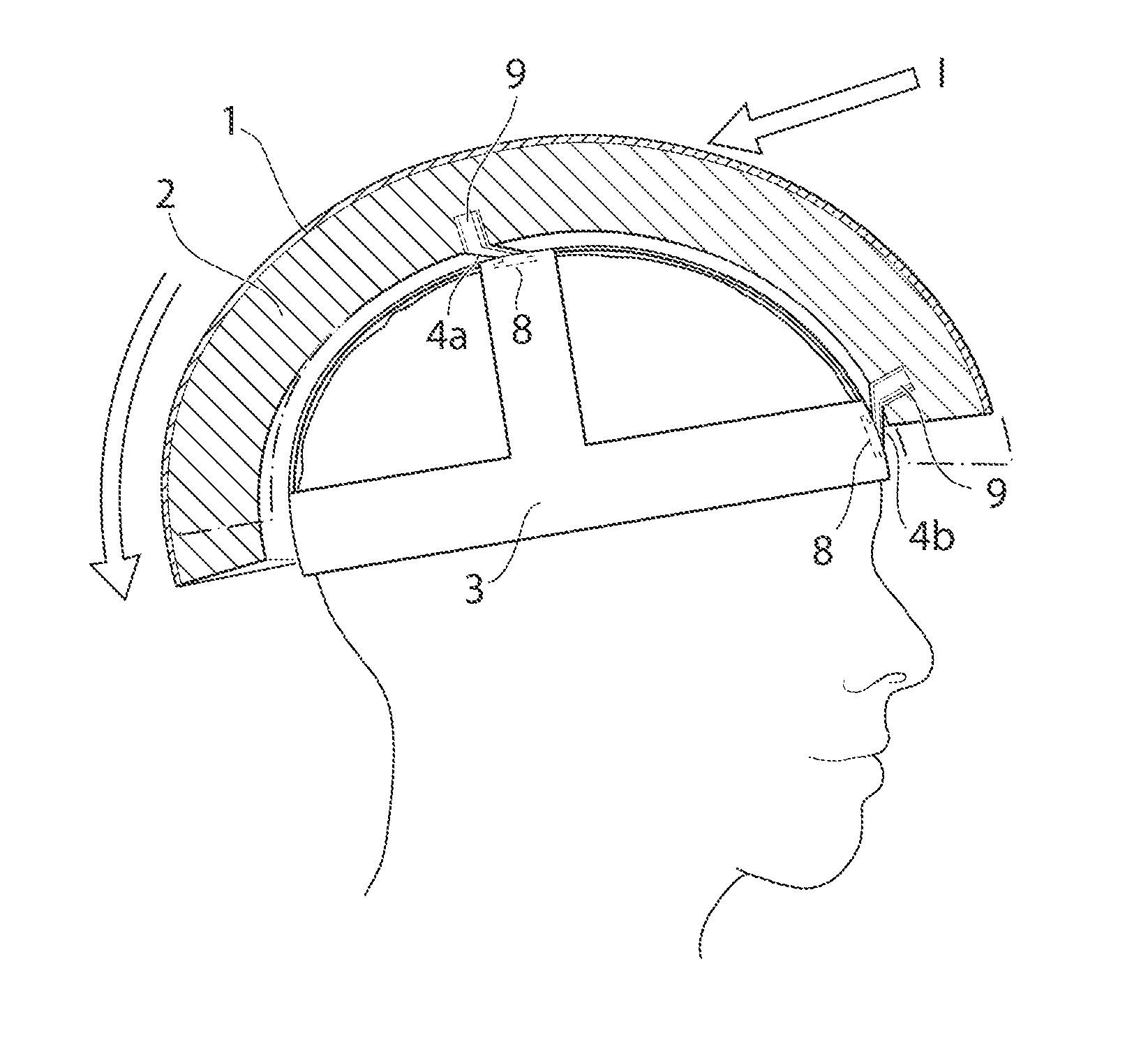
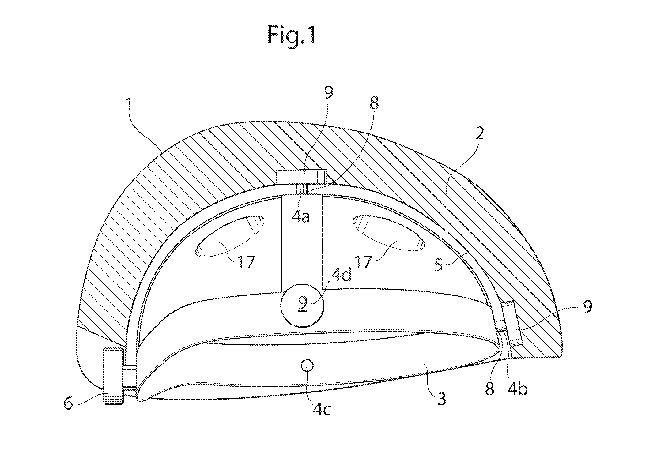
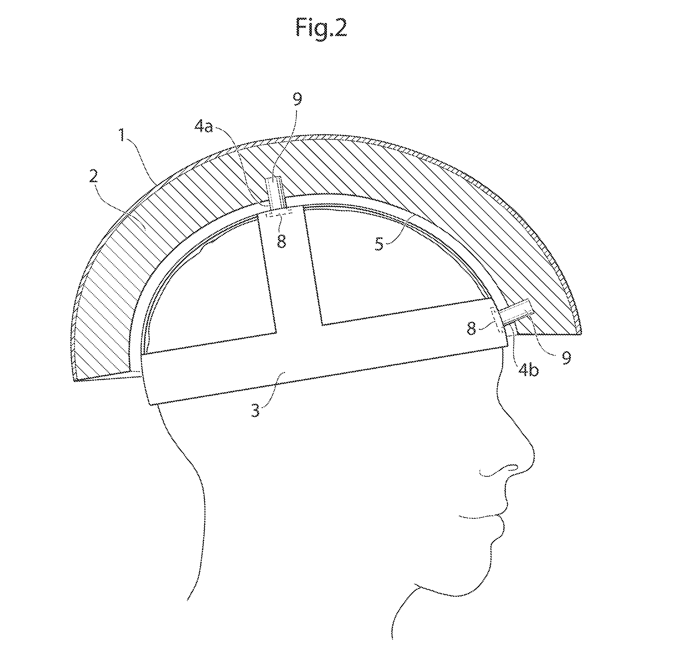
[0039]In the following a detailed description of embodiments will be given. It will be appreciated that the figures are for illustration only and are not in any way restricting the scope. Thus, any references to direction, such as “up” or “down”, are only referring to the directions shown in the figures.

[0040]One embodiment of a protective helmet comprises an energy absorbing layer, and a sliding facilitator being provided inside of the energy absorbing layer. According to one embodiment an in-mold helmet suitable for bicycling is provided. The helmet comprises an outer preferably thin, rigid shell made of a polymer material such as polycarbonate, ABS, PVC, glassfiber, Aramid, Twaron, carbonfibre or Kevlar. It is also conceivable to leave out the outer shell. On the inside of the shell an energy absorbing layer is provided which could be a polymer foam material such as EPS (expanded poly styrene), EPP (expanded polypropylene), EPU (expanded polyurethane) or other structures like hon...


PUM


Abstract

The present application provides a helmet. The helmet includes an energy absorbing layer (2) and a sliding facilitator (5). The sliding facilitator is provided on an inside surface of the energy absorbing layer (2). A method of manufacturing the helmet is further provided. The method includes the steps of: providing an energy absorbing layer in the mold, and providing a sliding facilitator contacting an inside surface of the energy absorbing layer.

Description

[0001]The present application is a national stage application claiming priority to International Application Serial Number PCT / SE2011 / 050556, filed May 3, 2011, which claims priority to U.S. Provisional patent application Ser. No. 61 / 333,817, filed May 12, 2010, and Swedish National Patent Application Serial Number 1050458-7, filed May 7, 2010.TECHNICAL FIELD[0002]The present invention relates generally to a helmet comprising an energy absorbing layer, with or without any outer shell, and a sliding facilitator being provided inside of the energy absorbing layer.BACKGROUND ART[0003]In order to prevent or reduce skull and brain injuries many activities requires helmets. Most helmets consist of a hard outer shell, often made of a plastic or a composite material, and an energy absorbing layer called a liner. Nowadays, a protective helmet has to be designed so as to satisfy certain legal requirements which relate to inter alia the maximum acceleration that may occur in the center of grav...

Claims


Application Information

Patent Timeline
Patent Type & Authority Patents(United States)
IPC IPC(8): A42B3/12A42B3/06A42B3/00
CPCA42B3/064A42B3/12A42B3/14A42B3/04A42B3/06A42B3/066A42B3/147A42B3/062A42B3/063A42B3/10A42B3/121A42B3/142A42B3/125A42B3/145
Inventor HALLDIN, PETER
Owner MIPS
Why Eureka
Try Eureka