Internal gear pump with optimized noise behaviour

a gear pump and noise behaviour technology, applied in the direction of rotary/oscillating piston pump components, machines/engines, liquid fuel engines, etc., can solve the problems of reducing the installation space, affecting the performance of the pump, and the occurrence of cavitation, so as to improve the filling and reduce cavitation , the effect of uniform maintenance of fluid characteristics

Inactive Publication Date: 2013-11-12
ZF FRIEDRICHSHAFEN AG
View PDF15 Cites 0 Cited by
  • Summary
  • Abstract
  • Description
  • Claims
  • Application Information

AI Technical Summary

Benefits of technology

[0006]Therefore, the inventive task is based on proposing of an internal gear pump, as in the above genus, where unwanted noise is avoided without increasing the required installation space.
[0008]Through the differently developed end pieces of the sickle shaped part, the filling at the low pressure side, or suction side, respectively, and also the outflow at the high pressure side, or pressure side, respectively, is significantly improved so that cavitations and the related generation of noise, in accordance with the invented internal gear pump, is avoided or at least reduced. The beginning of the cavitation is, therefore, moved, as a result of the different embodiments of the end pieces of the sickle shaped part, toward the higher rotational speed.
[0009]In accordance with a preferred embodiment of this invention, it is provided that at the low pressure side end piece of the sickle shaped part, or the like, the inlet area is modified in a way that the filling of the filling chambers is significantly improved so that, even at a higher pump rotational speed, a complete and possibly a fast filling of the filling chambers is ensured.
[0016]The proposed modifications at the sickle shaped part of the internal gear pump altogether improve the filling and reduce cavitations, while fluid characteristics are evenly maintained. Each proposed measure, for itself optimizes the internal gear pump in regard to developing cavitations and noise. The geometric modifications at the ends of the part are individually selected, depending on inlet pressure, the outlet pressure, the temperature of the fluid, and / or the rotation of the pump. Hereby, the measures in this invention increase the amount of working volume in the upper rotational speed area of the internal gear pump. In addition, the pressure gradient at the outlet area is reduced and, therefore, a significant reduction in the noise of the internal gear pump is achieved.
[0017]The internal gear pump, in accordance with the invention, is hereby operated within a large rotational speed range, in comparison to internal gear pumps known in the art, at little noise generation, or at the same rotational speed or at least similar noise generation with a correlating larger rotation speed, respectively. Through the inventive embodiment of the sickle shaped part of the inlet and outlet area, the internal gear pump is operated at lower, as well as at a higher pump rotational speed, at a minimal noise combined with a minimal volume flow loss.

Problems solved by technology

The meshing teeth do not allow a return flow of the fluid from the pressure side to the suction side.
A problem with these internal gear pumps is the occurrence of cavitation.
However, these measures cause, especially with automatic transmissions, disadvantages which are induced because of a resulting increase in the required installation space and the manufacturing cost.
There are also other limitations present in such a transmission system utilizing internal gear pumps.
These limitations also influence the embodiment of the pump so that it is difficult to optimize the internal gear pump in regard to cavitations and avoiding the noise, without here increasing the dimensions of the internal gear pump.

Method used


Image

  • Internal gear pump with optimized noise behaviour
  • Internal gear pump with optimized noise behaviour
  • Internal gear pump with optimized noise behaviour

Examples


Embodiment Construction

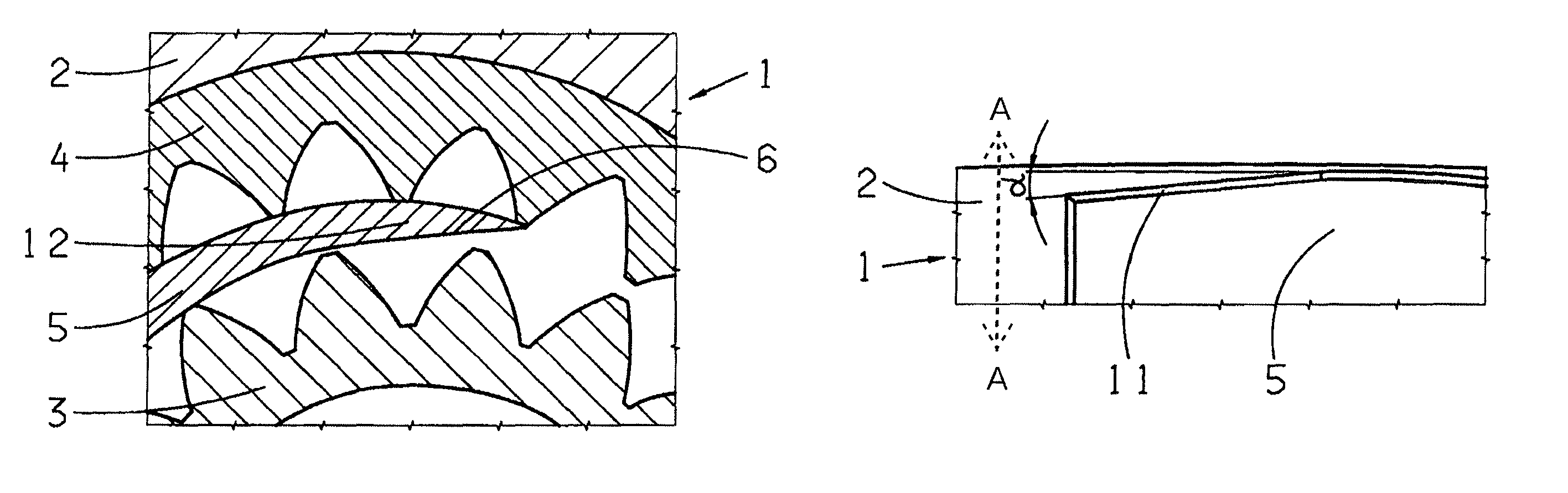
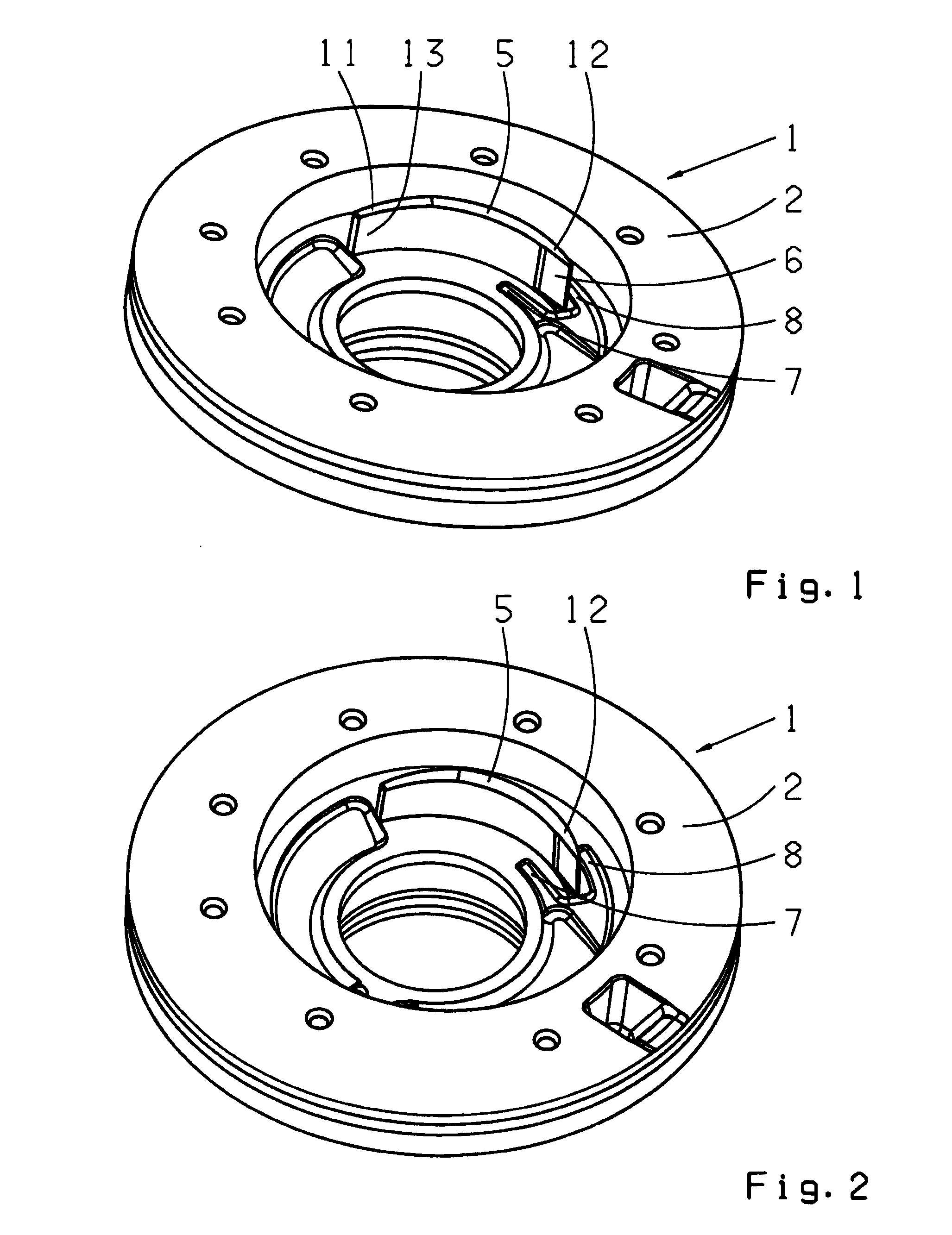
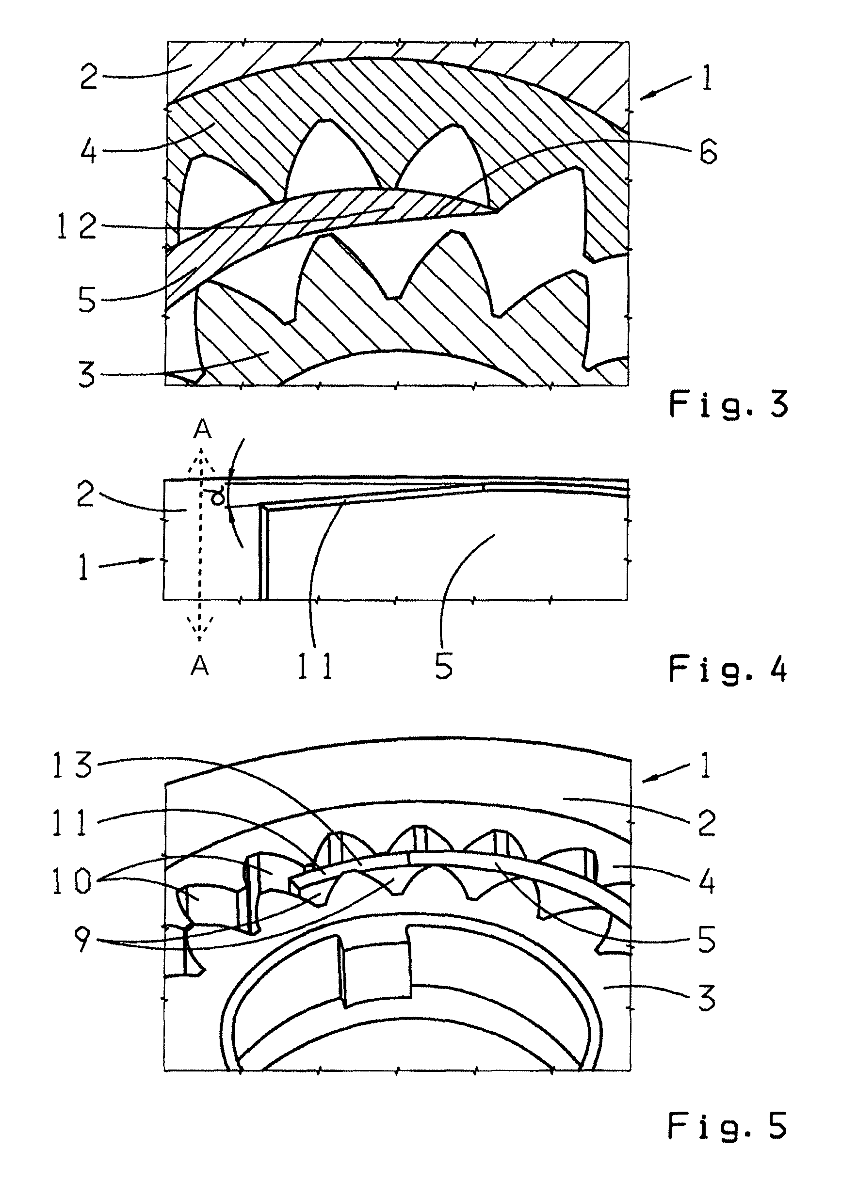
[0024]In FIG. 1 to FIG. 5, different perspective partial views of possible embodiments of this invention for the internal gear pump 1 are presented. For instance, the internal gear pump 1 can be applied to a vehicle automatic transmission, for converting a mechanical behavior, in the form of torque at a rotating shaft, into a hydraulic power. Thus, a higher predetermined pressure level can set for a fluid, such as oil. In this presented exemplary internal gear pump 1, the construction of the pump gear 3 is counter-clockwise. Hereby, the drawing plane shows the low level pressure side or suction side, respectively, on the right hand side and the high pressure side or pressure side, respectively, on the left hand side.

[0025]The internal gear pump 1 comprises an enclosure 2 in which the pump gear 3, driven by a drive shaft, and the ring gear 4 are rotatably mounted. The pump gear 3 and the ring gear 4 form a meshing area and a sealing area. Opposite the sealing area, a free space locat...


PUM


Abstract

An internal gear pump (1) is proposed for conveying a fluid by a driven pump gear wheel (3) and a ring gear (4), as a gear pair residing in an enclosure, which are, for instance, meshing and hereby generating a sealed area. Hereby, viewed cross-sectionally, a sickle shaped part (5) is provided for sealing the free space, located nearly opposite to the sealed area, whereby a first end piece (12) and a second end piece (13) of the part (5) are assigned to a high pressure area. In accordance with the invention, the two end pieces (12, 13) of the part (5) are constructed differently.

Description

[0001]This application claims priority from German application serial no. 10 2008 054 474.4 filed Dec. 10, 2008.FIELD OF THE INVENTION[0002]The present invention concerns an internal gear pump for conveying a fluid.BACKGROUND OF THE INVENTION[0003]Internal gear pumps mainly comprise an enclosure in which a gear wheel pair, having the smallest possible axial and radial play, is engaged and meshed for conveying a fluid, i.e., a pressure fluid or the like. Hereby, the suction side or lower pressure side, respectively, of the inner gear pump is linked to a fluid container, and the pressure side, or high pressure side, respectively, is linked with the hydro system which needs to be supplied. The gear wheel pair is formed by a inner rotor gear wheel and by a ring gear. The inner rotor gear wheel is driven by a motor, for instance, whereby the rotor gear, due to an active gear engaging, is turning and rotating the outer ring gear. Through this rotation, the gear teeth diverge from another ...

Claims


Application Information

Patent Timeline
Patent Type & Authority Patents(United States)
IPC IPC(8): F01C1/10F04C2/10F04C18/10
CPCF04C2/101F04C15/0019
Inventor ABU SAMRA, MUNEERRIEGERT, GERNOTSTEINBERGER, FLORIAN
Owner ZF FRIEDRICHSHAFEN AG
Why Eureka
Try Eureka