Process for fastening an accessory to a plastic hollow body during the molding thereof and a connection piece

a technology of plastic hollow body and connection piece, which is applied in the field of process for fastening an accessory to a plastic hollow body during the molding thereof, can solve the problems of reducing the working height of the tank, adversely affecting the weight of the tank, and reducing the sealing effect, so as to reduce the weight and reduce the weight. , the effect of good welding quality

Active Publication Date: 2013-11-12
PLASTIC OMNIUM ADVANCED INNOVATION & RES SA
View PDF23 Cites 7 Cited by
  • Summary
  • Abstract
  • Description
  • Claims
  • Application Information

AI Technical Summary

Benefits of technology

[0011]The present invention aims at solving these problems by providing a connector whose bulkiness and weight are reduced and which makes it possible to obtain a good welding quality despite a simple design.
[0013]The use of such a double lip (or one-piece part having two concentric curved edges, i.e., two protuberances located preferably at its periphery, which are concentric and are in relief relative to the remainder of the part) makes it possible to double the bond strength of the weld, this being with little material and via a part that is easy to mold as one piece with, or to fasten to, the coupling. It should be noted that this lip does not necessarily have to be solid but may comprise slots or other openings / perforations of any shape. It should also be noted that it does not have to be circular either and that it in fact depends generally on the shape of the stop surface, since it is preferably located on the circumference of the latter.

Problems solved by technology

Hence there may be potential sealing problems near this opening.
it is bulky and reduces the working height of the tank in the (frequent) case where the accessory must be located in the gas pocket over the liquid (and not be submerged)
it is relatively heavy and adversely affects the weight of the tank (and by doing so, that of the vehicle for which it is intended)

Method used


Image

  • Process for fastening an accessory to a plastic hollow body during the molding thereof and a connection piece
  • Process for fastening an accessory to a plastic hollow body during the molding thereof and a connection piece

Examples


Embodiment Construction

, reference will now be made to the accompanying drawing in which:

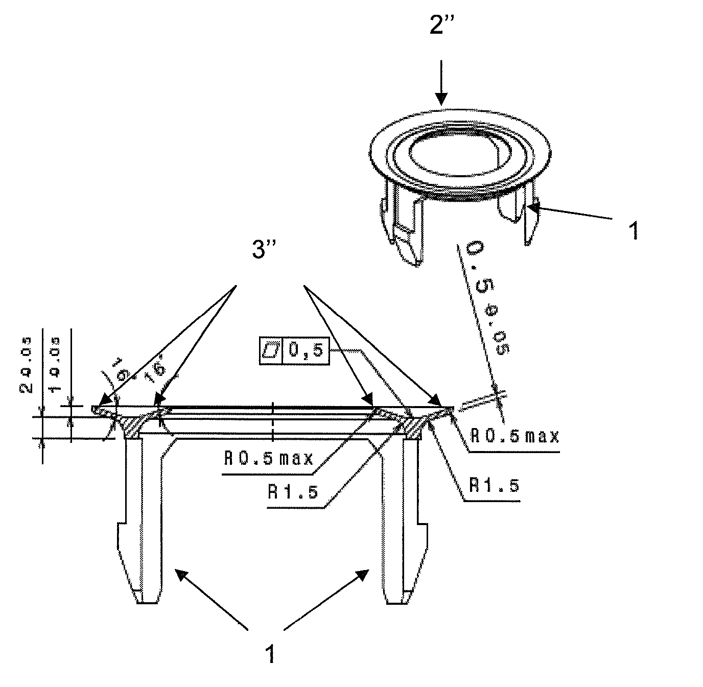
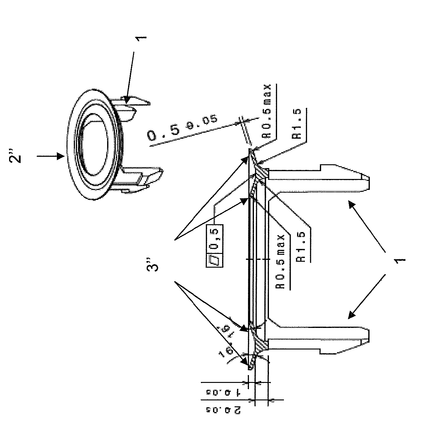
[0016]FIG. 1 illustrates a preferred connector geometry being that of a clip having fastening tabs that are intended to be inserted into an orifice of the accessory to be fastened and a cover which is in the form of a flat crown with a curved and tapered double edge.

DETAILED DESCRIPTION OF PREFERRED EMBODIMENTS

[0017]The term “FT” is understood to mean an impermeable tank, able to store fuel under diverse and varied usage and environmental conditions. An example of this tank is that with which motor vehicles are equipped.

[0018]The term “plastic” means any material comprising at least one synthetic resin polymer.

[0019]All types of plastic may be suitable. Particularly suitable are plastics that belong to the category of thermoplastics.

[0020]The term “thermoplastic” is understood to mean any thermoplastic polymer, including thermoplastic elastomers, and blends thereof. The term “polymer” is understood to mean both homopo...


PUM

PropertyMeasurementUnit
heightaaaaaaaaaa
heightaaaaaaaaaa
heightaaaaaaaaaa

Abstract

Process for fastening an accessory to a hollow body obtained by molding a molten plastic parison and using a plastic connector comprising coupling means for the accessory and a stop surface intended to limit the penetration of the connector into the molten plastic, according to which the stop surface is provided with a curved double lip (or one-piece part having two concentric curved edges, i.e., two protuberances located preferably at its periphery, which are concentric and are in relief relative to the remainder of the part) and the connector is welded to the inner wall of the parison using this double lip.

Description

CROSS-REFERENCE TO RELATED APPLICATIONS[0001]This application is a U.S. national stage application under 35 U.S.C. §371 of International Application No. PCT / EP2009 / 060195 filed Aug. 6, 2009, which claims priority to French Application No. FR 08.55458 filed Aug. 7, 2008, this application being herein incorporated by reference in its entirety for all purposes.TECHNICAL FIELD OF THE INVENTION[0002]The present invention relates to a process for fastening an accessory to a plastic hollow body (and in particular, a hollow body intended for a motor vehicle) during the manufacture, by molding, thereof and using a particular connector.BACKGROUND OF THE INVENTION[0003]Fuel tanks on board vehicles of various kinds generally have to meet sealing and permeability standards in relation to the type of use for which they are designed and the environmental requirements that they have to satisfy. At the present time, both in Europe and throughout the world, there is a substantial tightening of the re...

Claims


Application Information

Patent Timeline
Patent Type & Authority Patents(United States)
IPC IPC(8): F16B2/20B23P11/02B29C65/70
CPCB29C49/20B29C51/12B29C65/028B29C66/61B29C49/0047B29C51/267B29C65/58B29C65/609B29C2049/0057B29C2049/2008B29C2049/2047B29C2049/206B29C2049/2073B29K2021/003B29K2023/00B29K2023/065B29K2023/086B29K2067/00B29K2077/00B29K2101/12B29K2223/00B29K2995/0067B29K2995/0069B29L2009/00B29L2031/7172B29C66/474B29C66/532B29C66/71Y10T29/49876Y10T24/44991B29C66/72343B29C66/72341B29C49/06914B29C49/0691B29C2049/4881B29K2061/00
Inventor JANNOT, FREDERICCRIEL, BJORNTARDY, PIERRE-FRANCOISPOHLMANN, RALPH
Owner PLASTIC OMNIUM ADVANCED INNOVATION & RES SA
Why Eureka
Try Eureka