Method for discharging liquid body, method for manufacturing color filter, and method for manufacturing organic EL device

a technology of liquid body and manufacturing method, which is applied in the manufacture of electric discharge tubes/lamps, electrode systems, resistive material coatings, etc., can solve the problems of uneven thickness of thin films, uneven discharge amount of liquid bodies, and deterioration of image quality of manufactured displays, so as to reduce the uneven thickness of light emitting layers and high productivity

Active Publication Date: 2013-11-12
KATEEVA
View PDF11 Cites 3 Cited by
  • Summary
  • Abstract
  • Description
  • Claims
  • Application Information

AI Technical Summary

Benefits of technology

[0011]According to the method of the first aspect, the droplet discharge heads having the nozzle line can be arranged in the same direction as that of the short side of a nearly rectangular shape of the first discharged region having a large area, and in the same direction as that of the long side of a nearly rectangular shape of the second discharged region having a small area. That is, the nozzles can be arranged in a direction of the short side of the nearly rectangular shape of the first discharged region having the large area and in a direction of the long side of the nearly rectangular shape of the second discharged region having the small area. Therefore, even if the first discharged region and the second discharged region that have the different areas from each other are mixed in a single substrate, more number of nozzles, which can discharge the liquid body in the discharged regions, can be allocated. This reduces concentrated discharge of the liquid body to a certain part in the discharged region and resulting imbalance of the discharge amount of the liquid body. Consequently, unevenness of thickness of thin films formed in the discharged regions can be reduced. Accordingly, the method enables at least two kinds of thin films to be manufactured with stable quality, contributing to improve the productivity of the films.
[0013]According to the method, the plurality of nozzles can be allocated opposed to the first discharged region so as to discharge the liquid body to the first discharged region. Therefore, even if a discharge property varies in the nozzles, the variation of the discharge property can be dispersed by using a plurality of nozzles. Consequently, unevenness of thickness of thin films formed in the discharged regions can be reduced.
[0015]According to the method, the arranging pitch between the droplets arranged in the direction of the short side of the first discharged region can be practically narrowed by disposing the nozzle line of the droplet discharge heads at an angle with the direction of the short side of the first discharged region. That is, more number of nozzles can be allocated opposed to the first discharged region so as to discharge the liquid body to the first discharged region. This reduces concentrated discharge of the liquid body to a certain part in the discharged region and resulting imbalance of the discharge amount of the liquid body. Consequently, unevenness of thickness of thin films formed in the discharged regions can be reduced.
[0017]According to the method, in the discharging, the liquid body can be discharged from the nozzles to the discharged regions while the droplet discharge heads and the substrate are relatively moved in the sub scan direction which is orthogonal to the main scan direction, that is, while a line feeding is performed. For example, the number of droplets which can be arranged in the direction of the short side of the first discharged region can be practically increased. This reduces concentrated discharge of the liquid body to a certain part in the discharged region and resulting imbalance of the discharge amount of the liquid body. Consequently, unevenness of thickness of thin films formed in the discharged regions can be reduced.
[0019]The method of the second aspect can reduce unevenness of the thickness of the colored layers formed in the first discharged region and the second discharged region having arranging directions orthogonal to each other, and manufacture at least two kinds of color filters, which include colored layers having different arranging directions from each other, with high productivity.
[0021]The method of the third aspect can reduce unevenness of the thickness of the light emitting layers formed in the first discharged region and the second discharged region having arranging directions orthogonal to each other, and manufacture at least two kinds of organic EL devices, which have organic EL elements arranged in different directions from each other, with high productivity.

Problems solved by technology

In this case, nozzles which can discharge the liquid body to the region are limited, and therefore the liquid body is discharged to a certain part of the region, causing uneven discharge amount of the liquid body.
The uneven discharge amount of the liquid body may cause uneven thickness of a thin film formed in the region.
The uneven thickness of the thin film such as functional films of color filters of liquid crystal displays and organic EL devices causes deterioration of the image quality of manufactured displays.
This reduces concentrated discharge of the liquid body to a certain part in the discharged region and resulting imbalance of the discharge amount of the liquid body.

Method used


Image

  • Method for discharging liquid body, method for manufacturing color filter, and method for manufacturing organic EL device
  • Method for discharging liquid body, method for manufacturing color filter, and method for manufacturing organic EL device
  • Method for discharging liquid body, method for manufacturing color filter, and method for manufacturing organic EL device

Examples


first example

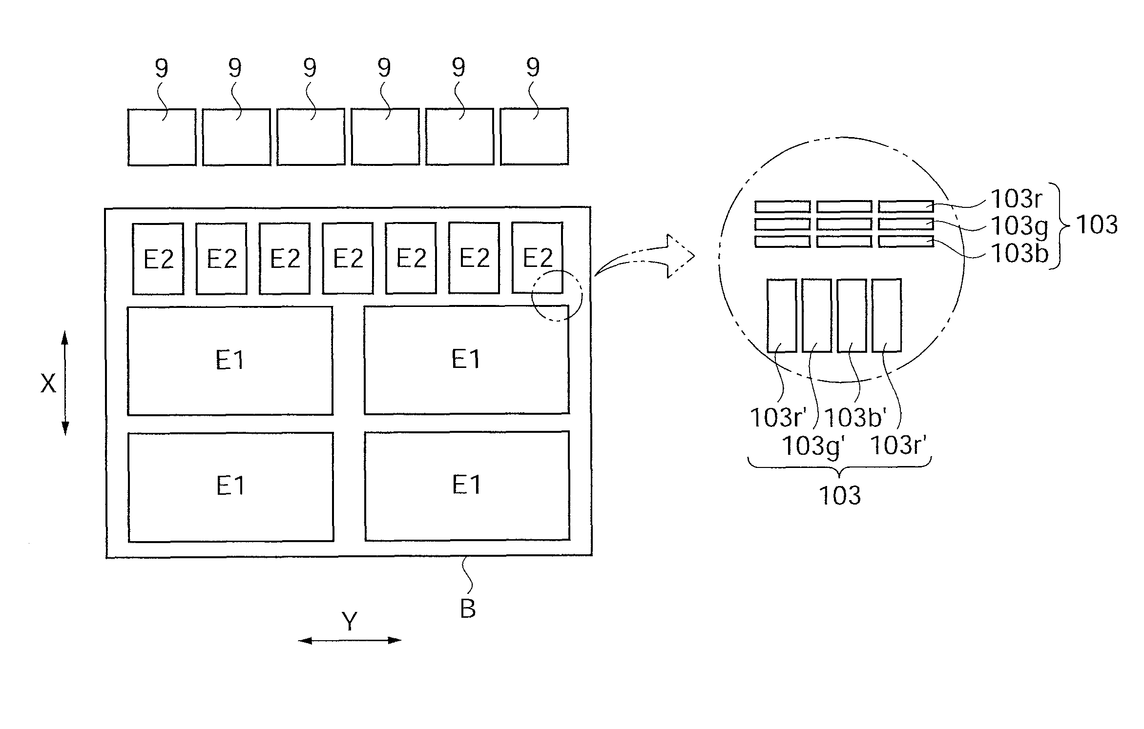
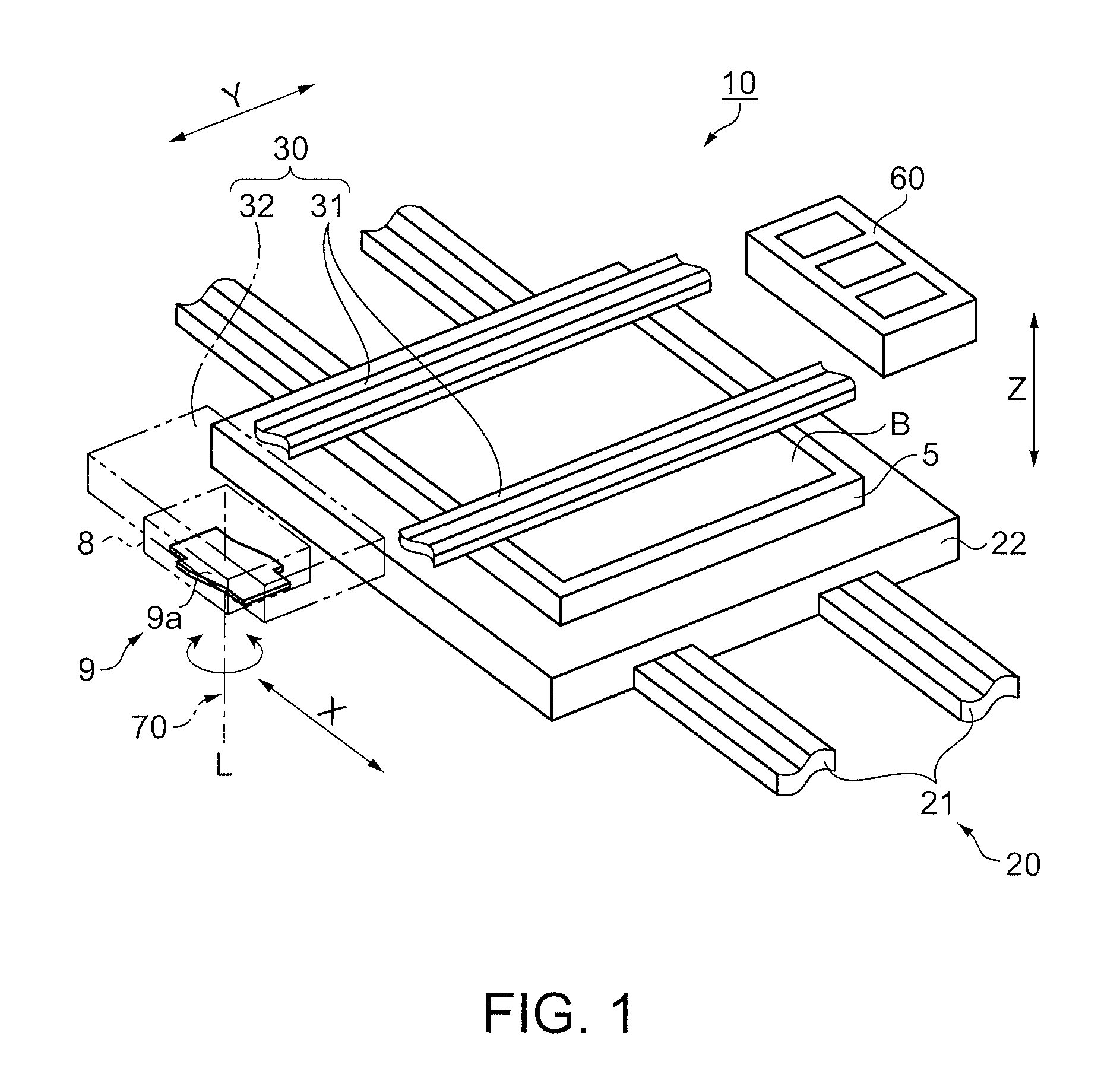
[0079]A method for manufacturing a color filter of a first example is described with reference to FIG. 8 to FIG. 9B. FIG. 8 is a schematic plan view showing a relative arrangement between the head unit and the mother substrate in the liquid body discharge step. FIGS. 9A and 9B are schematic plan views showing an arrangement of droplets in the liquid body discharge step. The X direction and the Y direction shown in FIG. 8 to FIG. 9B respectively indicate the same direction as the X direction and the Y direction in FIG. 1.

[0080]As shown in FIG. 8, a mother substrate B of the first example has second panels E2 arranged in a plural manner (seven) along a long side of the mother substrate B, and first panels E1 arranged in a matrix (four) along the long side and a short side of the mother substrate B. The second panel E2 has an area smaller than that of the first panel E1.

[0081]In the second panels E2, the film forming regions 103r, 103g, and 103b, each having a rectangular shape and ser...

second example

[0090]A method for manufacturing a color filter of a second example is described with reference to FIG. 10 to FIG. 11B. FIG. 10 is a schematic plan view showing a relative arrangement between a head unit and a mother substrate in the liquid body discharge step in the second example. FIGS. 11A and 11B are schematic plan views showing an arrangement of droplets in the liquid body discharge step of the second example. The X direction and the Y direction shown in FIG. 10 to FIG. 11B respectively indicate the same direction as the X direction and the Y direction in FIG. 1. The same numeral is given to the same structure as the first example employs, and the description thereof is omitted.

[0091]The mother substrate of the second example has seven plates of second panels E2 and four plates of first panels E1 as is the case with the first example. A plurality of film forming regions 103r, 103g, and 103b serving as the second discharged regions and having rectangular shapes are arranged in a...

third example

[0102]A method for manufacturing a color filter of a third example is described with reference to FIGS. 12A to 12C. FIGS. 12A to 12C are schematic plan views showing an arrangement of droplets in the liquid body discharge step of the third example. The X direction and the Y direction shown in FIGS. 12A to 12C respectively indicate the same direction as the X direction and the Y direction in FIG. 1. The same numerals are given to the same structures as the first and second examples employ, and the description thereof is omitted.

[0103]A mother substrate of the third example has seven plates of second panels E2 and four plates of first panels E1 likewise the mother substrate B in the first and second examples. A plurality of film forming regions 103r, 103g, and 103b serving as the second discharged regions and having rectangular shapes are arranged in a matrix in the second panels E2, and a plurality of film forming regions 103r′, 103g′, and 103b′ serving as the first discharged region...


PUM

PropertyMeasurementUnit
angleaaaaaaaaaa
thicknessaaaaaaaaaa
thicknessaaaaaaaaaa

Abstract

A method for discharging a liquid body includes: discharging the liquid body to a discharged region from a plurality of nozzles while a plurality of droplet discharge heads having a nozzle line having the plurality of nozzles that discharge the liquid body as droplets and are arranged in a linear manner, and a substrate including a plurality of discharged regions having a nearly rectangular shape are relatively moved in a main scan direction that is nearly orthogonal to an arrangement direction of the droplet discharge heads. In the method, the plurality of discharged regions are composed of a first discharged region and a second discharged region. The first discharged region is disposed on the substrate to set a long side thereof along a certain direction, and the second discharged region has a smaller area than the first discharged region and is disposed to set a long side thereof nearly orthogonal to the long side of the first discharged region. Further, the first discharged region is disposed to set the long side thereof along the main scan direction in the discharging.

Description

CROSS-REFERENCE TO RELATED APPLICATIONS[0001]This application claims priority to Japanese Application No. 2008-267144 filed on Oct. 16, 2008. The entire disclosure of Japanese Application No. 2008-267144 is incorporated herein by reference.BACKGROUND[0002]1. Technical Field[0003]The present invention relates to a method for discharging a liquid body which is discharged from a nozzle, a method for manufacturing a color filter, and a method for manufacturing an organic EL device.[0004]2. Related Art[0005]Methods for discharging a liquid body containing a functional material are applied to form films for color filters of liquid crystal displays and organic EL devices, for example. A liquid body discharge device is used to discharge the liquid body. The liquid body discharge device includes a droplet discharge mechanism called a droplet discharge head. The droplet discharge head has a plurality of nozzles arranged in a regular manner. In manufacturing the color filters and organic EL de...

Claims


Application Information

Patent Timeline
Patent Type & Authority Patents(United States)
IPC IPC(8): B05D5/06
CPCB41J2/14233B41J2/145G02B5/201H01L27/3211H01L51/0005H01L51/56H10K59/35H10K71/135H10K71/00
Inventor SHINOHARA, TORU
Owner KATEEVA
Why Eureka
Try Eureka