
Test point structure for RF calibration and test of printed circuit board and method thereof

a technology of printed circuit board and point structure, which is applied in the direction of high frequency circuit adaptation, inspection/indentification of circuits, instruments, etc., can solve the problems of high price of rf switches and increase manufacturing costs, and achieve the effect of saving manufacturing costs of mobile communication terminals

Inactive Publication Date: 2013-11-12
SAMSUNG ELECTRONICS CO LTD
View PDF5 Cites 5 Cited by
  • Summary
  • Abstract
  • Description
  • Claims
  • Application Information

AI Technical Summary

Benefits of technology

The present invention provides a test point structure that saves manufacturing costs of a mobile communication terminal. It also provides a method for RF calibration and testing of a PCB that reduces costs.

Problems solved by technology

However, in an aspect of manufacturing costs, the price of the RF switch is high, which results in a manufacturing cost increase.

Method used


Image

  • Test point structure for RF calibration and test of printed circuit board and method thereof
  • Test point structure for RF calibration and test of printed circuit board and method thereof
  • Test point structure for RF calibration and test of printed circuit board and method thereof

Examples


Embodiment Construction

[0023]The following description with reference to the accompanying drawings is provided to assist in a comprehensive understanding of exemplary embodiments of the invention as defined by the claims and their equivalents. It includes various specific details to assist in that understanding but these are to be regarded as merely exemplary. Accordingly, those of ordinary skill in the art will recognize that various changes and modifications of the embodiments described herein can be made without departing from the scope and spirit of the invention. Also, descriptions of well-known functions and constructions are omitted for clarity and conciseness.

[0024]The terms and words used in the following description and claims are not limited to the bibliographical meanings, but, are merely used by the inventor to enable a clear and consistent understanding of the invention. Accordingly, it should be apparent to those skilled in the art that the following description of exemplary embodiments of ...


PUM


Abstract

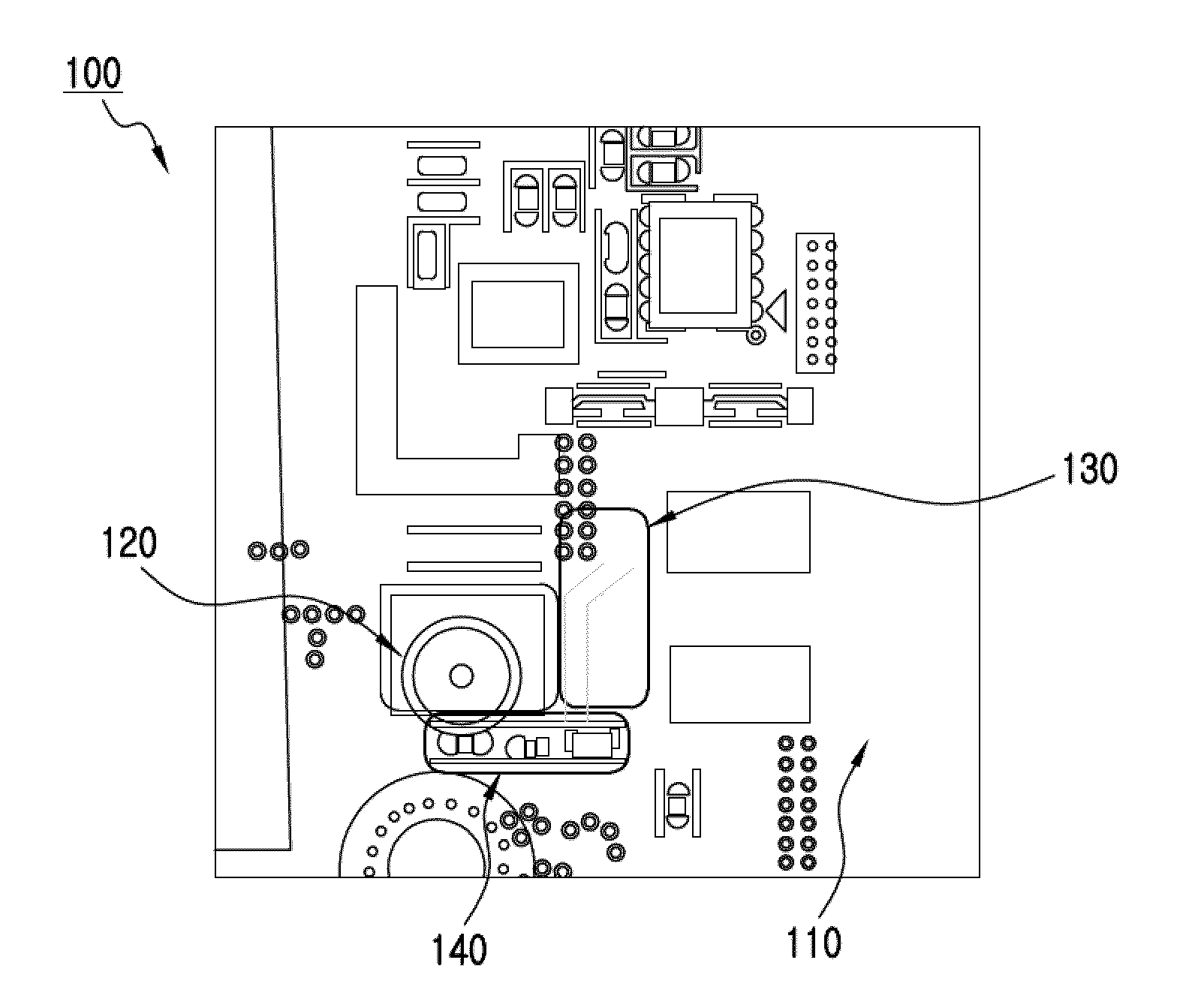
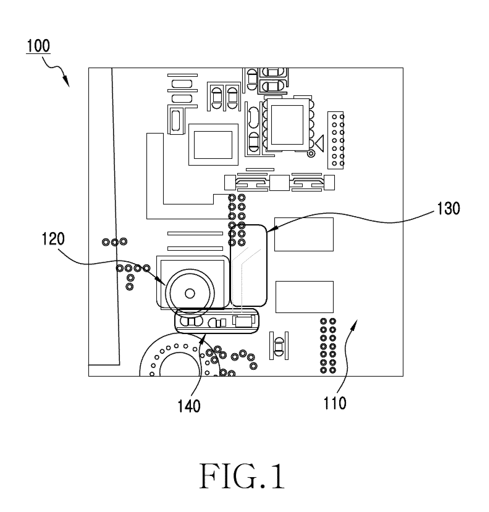
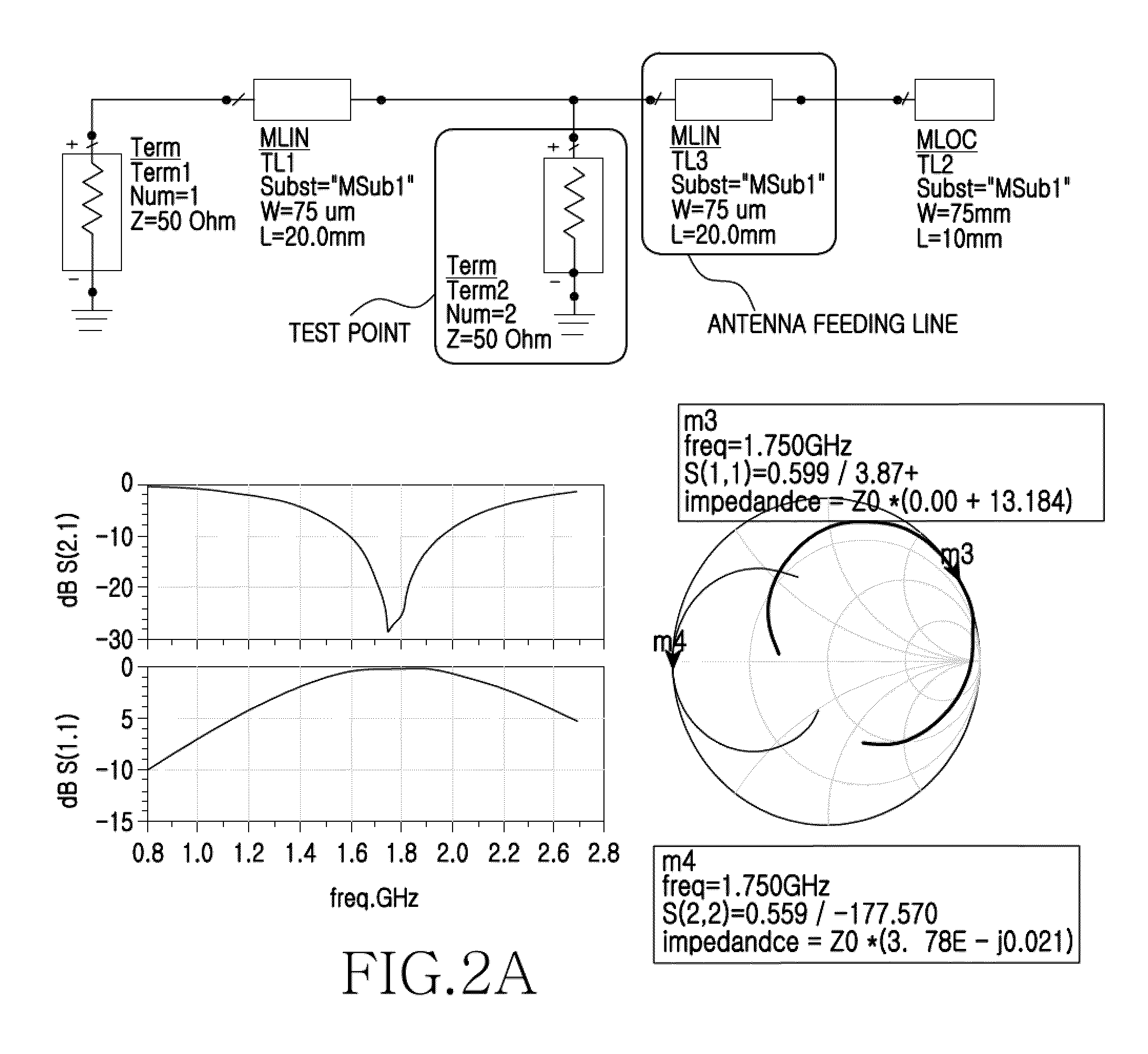
A point structure for RF calibration and testing of a PCB is provided. The point structure includes a test pad, an antenna connection pad, and a device mounting pad. The test pad is connected to a circuit unit of the PCB, and a ground pad is connected with a ground of the PCB. A contact probe apparatus for performing RF calibration and testing is connected to the test pad and the ground pad. The antenna connection pad is connected to an antenna unit. The device mounting pad is connected with the test pad and the antenna connection pad. An antenna device is mounted on the device mounting pad. The test pad, the ground pad, the antenna connection pad, and the device mounting pad are separated from one another. Since the point structure can replace an RF switch, a circuit area on the PCB may be reduced, a mounting space may be secured, and a manufacturing cost may be reduced.

Description

PRIORITY[0001]This application claims the benefit under 35 U.S.C. §119(a) of a Korean patent application filed in the Korean Intellectual Property Office on Nov. 20, 2008 and assigned Serial No. 10-2008-0115689, the entire disclosure of which is hereby incorporated by reference.BACKGROUND OF THE INVENTION[0002]1. Field of the Invention[0003]The present invention relates to a point structure for Radio Frequency (RF) calibration and testing of a Printed Circuit Board (PCB) and a method thereof. More particularly, the present invention relates to a test point structure for RF calibration and testing of a PCB and a method thereof, to reduce manufacturing costs.[0004]2. Description of the Related Art[0005]Generally, a mobile communication terminal includes a Printed Circuit Board (PCB). The PCB includes a circuit unit, comprising a plurality of integrated circuits and various chips, for converting data into a signal that is suitable for transmission / reception, and for transmitting the si...

Claims


Application Information

Patent Timeline
Patent Type & Authority Patents(United States)
IPC IPC(8): G01R31/00
CPCG01R31/2818G01R35/005H05K1/0268G01R31/2822H05K1/0237H05K2201/10098G01R31/28
Inventor KIM, YOUNG-JU
Owner SAMSUNG ELECTRONICS CO LTD
Learn More