Portable equipment detecting system

a technology of portable equipment and detection system, applied in the field of communication systems, can solve the problems of inability to detect the location of portable equipment and complicated configuration, and achieve the effect of simple configuration and fast response tim

Active Publication Date: 2013-11-12
DENSO CORP
View PDF11 Cites 12 Cited by
  • Summary
  • Abstract
  • Description
  • Claims
  • Application Information

AI Technical Summary

Benefits of technology

[0011]An embodiment provides a portable equipment detecting system in which location of the portable equipment is detected with a fast response time and with a simple configuration.
[0016]Thus, according to the above-described detecting system, since only the supplied state to the two-axis (first element and second element) antenna is switched three times, the portable equipment can be detected by using simple configuration and also, the location of the portable equipment can be detected with fast response time.
[0021]When the battery is used for the portable equipment as a power source, it is considered that the communication between the detecting system and the portable equipment may not be reliably made due to consumption of the battery. In this case, a backup apparatus can be provided in the detecting system to secure the communication between the portable equipment and the portable equipment. This backup apparatus can be arranged at a portion where the portable equipment can be placed in the vehicle. The backup apparatus generates electromagnetic field to be used for the portable equipment when the portable equipment does not return an acknowledge signal nevertheless a start switch disposed in the passenger's cabin is turned ON. Meanwhile, the portable equipment includes a generation circuit for generating electromotive force, and the generation circuit is configured to generate the electromotive force by the electromagnetic field generated by the backup circuit. Therefore, even when the battery power of the portable equipment has been consumed, the communication between the portable equipment detecting system and the portable equipment can be maintained.
[0023]In this way, an antenna used for the communication between the detecting system and the portable equipment, and an antenna used for the backup can be integrated whereby the number of antennas can be reduced.

Problems solved by technology

However, location of the portable equipment cannot be detected by this procedure.
Moreover, a mechanism used for rotating the transmission / reception is necessary so that the configuration may become complicated.

Method used


Image

  • Portable equipment detecting system
  • Portable equipment detecting system
  • Portable equipment detecting system

Examples


first embodiment

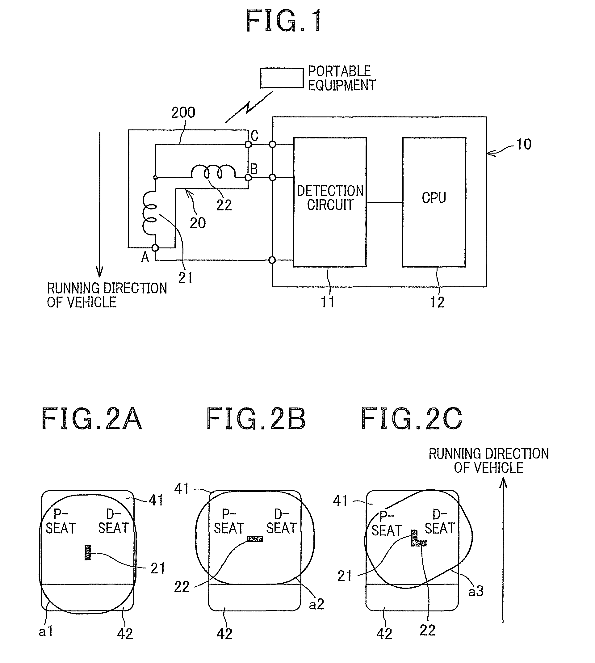
[0042]With reference to FIGS. 1 to 3, a portable equipment detecting system according to a first embodiment of the present invention is described as follows. FIG. 1 is a block diagram showing an overall configuration of the portable equipment detecting system according to the first embodiment.

[0043]The portable equipment detecting system according to the first embodiment is mounted on the vehicle and configured to mutually communicate with the portable equipment thereby detecting the location of the portable equipment. This portable equipment detecting system is applied to, for example, a smart entry system which is used to control doors of the vehicle to be locked / unlocked based on a verification result of an identification (ID) code exchanged between the detecting system and the portable equipment via a bidirectional communication (mutual communication), and a smart start system which is used to control lock / unlock of the steering and enable / disable starting the engine.

[0044]As sh...

second embodiment

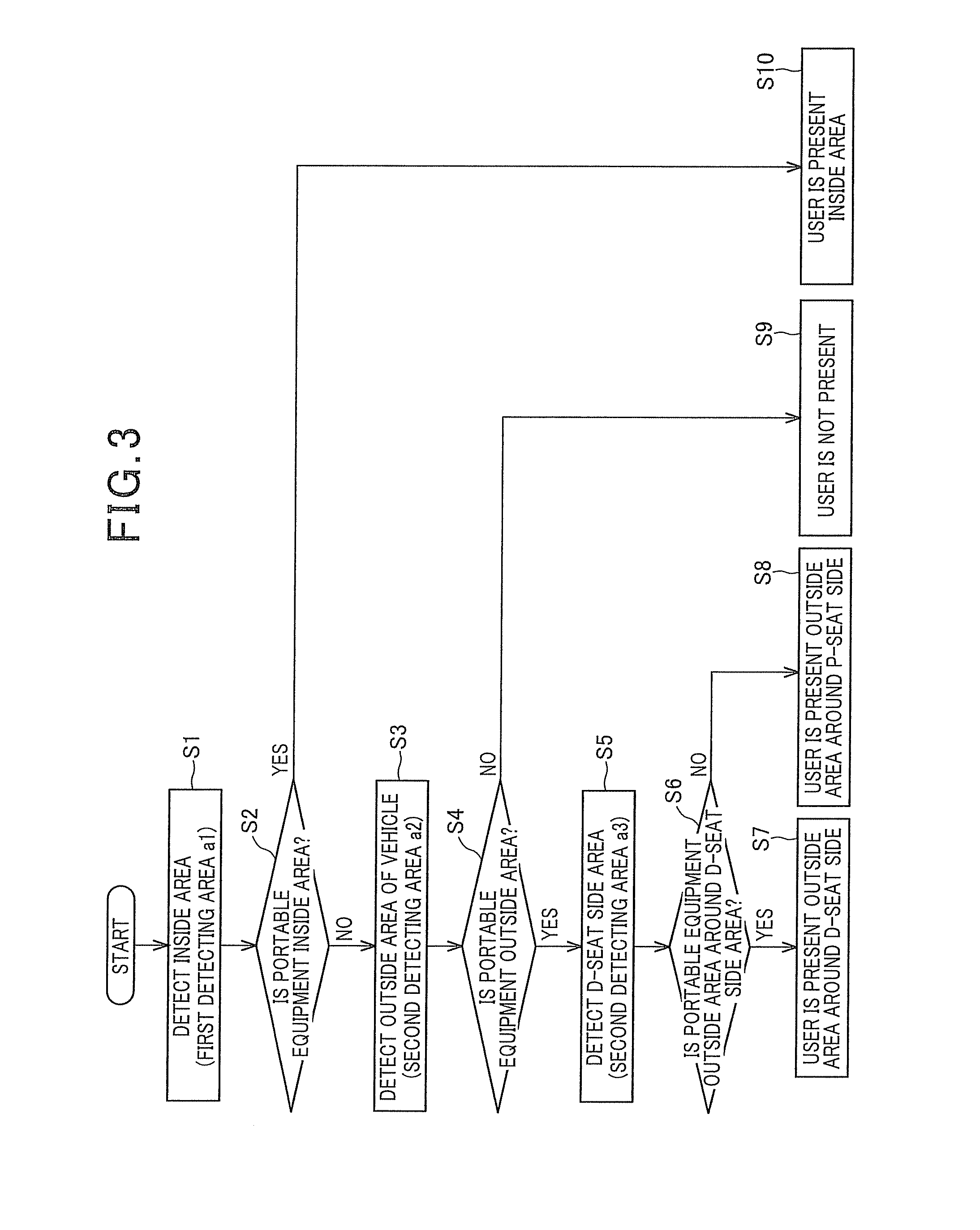
[0066]Next, with reference to FIG. 6, the portable equipment detecting system according to the second embodiment of the present invention is described. The overall configuration portable equipment detecting system according to the second embodiment is the same as the one of the first embodiment. Hence, the explanation thereof is omitted (Please see FIG. 1). Regarding the operation procedure of the portable equipment detecting system according to the second embodiment, since most function blocks are identical to the function blocks of the first embodiment, the explanation for the identical blocks is omitted. In the flowchart as shown in FIG. 6, steps having the same contents of the flowchart as shown in FIG. 3 have the same step number. It is noted that the difference between the portable equipment detecting system according to the first embodiment and the portable equipment detecting system according to the second embodiment is whether or not the portable equipment is in the trunk s...

third embodiment

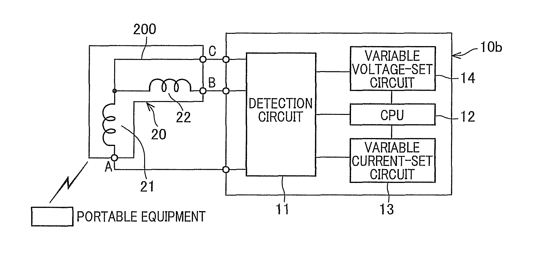
[0070]Next, with reference to FIGS. 7 to 9, hereinafter will be described a portable equipment detecting system according to a third embodiment. Since most function blocks configures the third embodiment are identical to the one of the above-described first embodiment, explanation thereof is omitted. For instance, in a block diagram as shown in FIG. 7, function blocks identical to those of the first embodiment are applied with the same reference numbers as the blocks in FIG. 1. The portable equipment detecting system according to the third embodiment differs from the one of the first embodiment in the power-supplied states, that is, a variable current-set circuit 13 and a variable voltage-set circuit 14 are added to the configuration used to make additional power-supplied states for the antenna 20 (i.e., first element 21 and second element 22), a fourth power-supplied state and a fifth power-supplied state.

[0071]As shown in FIG. 7, the portable equipment detecting system includes th...


PUM


Abstract

A portable equipment detecting system includes an antenna having a first element of which a longitudinal direction is defined as a running direction of the vehicle, a second element of which longitudinal direction is defined as a direction perpendicular to the running direction of the vehicle and the vertical direction of the vehicle, and a bypass wiring of which one end is connected to a connection point between the first and second elements; and detecting circuit adapted to switch between three power-supplied states of the antenna including a first supplied state, a second supplied state and a third supplied state, and to detect a location of the portable equipment based on an acknowledge signal from the portable equipment when the power-supplied state is switched.

Description

CROSS REFERENCE TO RELATED APPLICATION[0001]This application is based on and claims the benefit of priority from earlier Japanese Patent Application No. 2010-056517 filed on Mar. 12, 2010, the description of which is incorporated herein by reference.BACKGROUND OF THE INVENTION[0002]1. Field of the Invention[0003]The present invention relates to communication systems mounted on vehicles, and more particularly to an on-vehicle wireless communication system for detecting a portable equipment mutually communicable with a communication apparatus mounted on a vehicle.[0004]2. Description of the Related Art[0005]Conventionally, a communication apparatus for vehicles have been employed to communicate with various portable equipments. Particularly, a Japanese Patent Application Laid-Open publication No. 2007-132119 discloses a communication apparatus for vehicle in which a portable equipment and an on-vehicle equipment are communicable with each other with less number of on-vehicle antennas....

Claims


Application Information

Patent Timeline
Patent Type & Authority Patents(United States)
IPC IPC(8): G08B25/00B60R25/10B60R25/24B60R25/40E05B49/00G01S7/02G01S13/74H01Q1/32H01Q3/24H03J9/02H04Q9/00
CPCG07C9/00309H04B17/27G07C2209/63G07C2009/00793E05B47/00B60R25/10B60R25/00
Inventor KOJIMA, MASAHITONAKASHIMA, KAZUHIROKUMAZAKI, TAKESHI
Owner DENSO CORP
Why Eureka
Try Eureka