Time of flight backscatter imaging system

a backscatter imaging and time-of-flight technology, applied in material analysis using wave/particle radiation, instruments, nuclear engineering, etc., can solve the problem of not being as well suited to scanning aircraft or even cars

Active Publication Date: 2013-11-12
RAPISCAN SYST INC (US)
View PDF10 Cites 52 Cited by
  • Summary
  • Abstract
  • Description
  • Claims
  • Application Information

AI Technical Summary

Problems solved by technology

They are not, however, as well suited for scanning aircrafts or even cars which have oval or elliptical cross-sections because, as a collimated beam scans an oval or cylindrical surface, some portions of the scanned surface are located closer to the photon detector(s) than other portions.
For the same reason, producing accurate and distortion-free images when screening luggage (such as on a conveyer system) and even when screening people, remains a challenge for backscatter X-ray imaging systems.

Method used


Image

  • Time of flight backscatter imaging system
  • Time of flight backscatter imaging system
  • Time of flight backscatter imaging system

Examples


Embodiment Construction

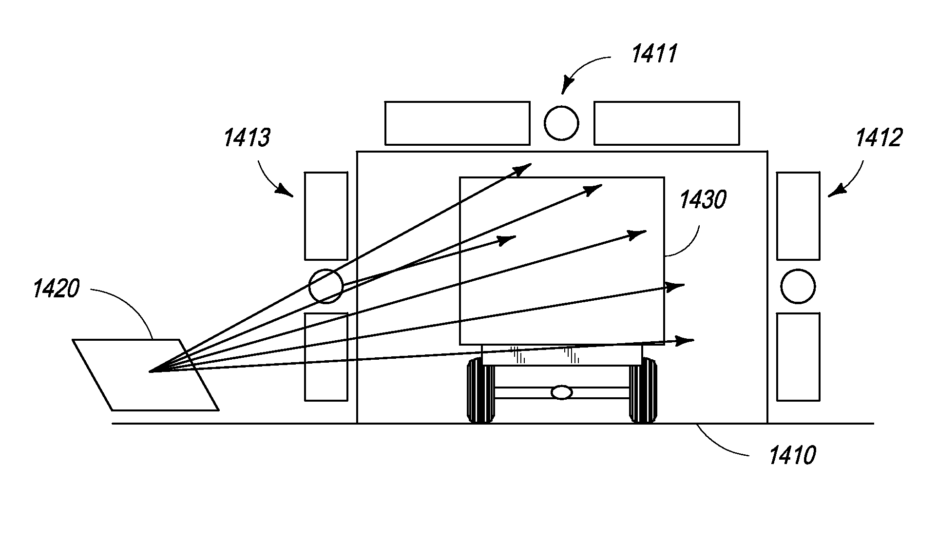
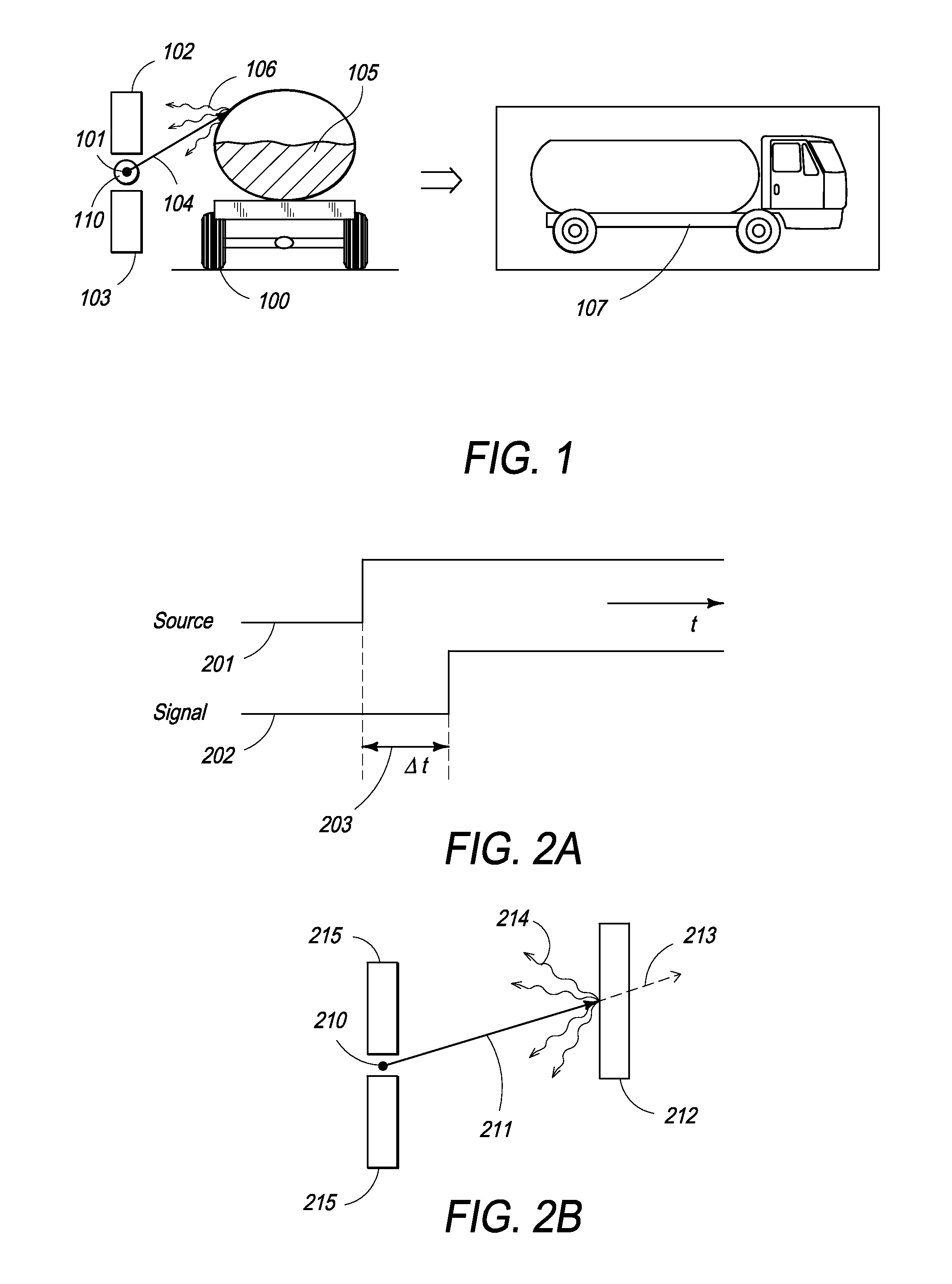
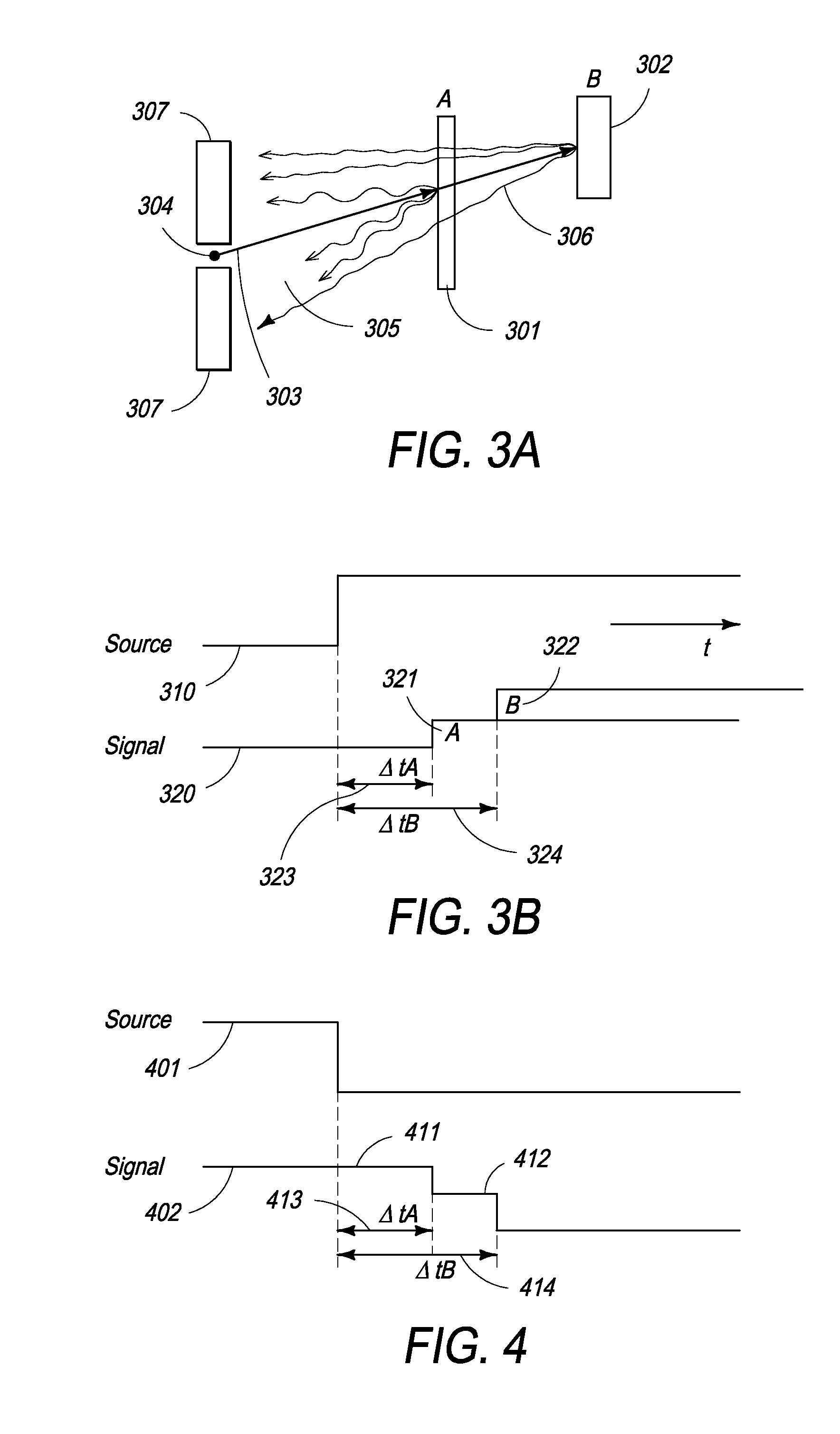
[0040]The present invention is a time of flight backscatter system which uses the finite velocity of the X-ray signal to determine the distance from the X-ray source to the surface of the object such that the surface profile of the object may be determined. The system of present invention provides an accurate spatial representation of backscattering from the object to be scanned and eliminates the assumption of straight sided objects on which conventional X-ray backscatter imaging systems are based. Knowledge of the surface profile provides a further inspection result which may be used to verify the integrity of the object under inspection.

[0041]Although one embodiment of the present invention is described with reference to X-ray scanning, one of ordinary skill in the art would appreciate that object screening may be performed using any available radiation imaging technique such as, but not limited to X-ray scattering, infrared imaging, millimeterwave imaging, RF imaging, radar imag...


PUM

PropertyMeasurementUnit
distanceaaaaaaaaaa
distanceaaaaaaaaaa
off timeaaaaaaaaaa

Abstract

The present application discloses an X-ray imaging apparatus for determining a surface profile of an object under inspection that is positioned at a distance from the apparatus. The X-ray imaging system has an X-ray source for producing a scanning beam of X-rays directed toward the object, a detector assembly for providing a signal representative of an intensity of X-rays backscattered from the object, and processing circuitry to determine a time difference between when the X-ray source is switched on and when the backscattered X-rays arrive at the detector assembly. The processing circuitry is adapted to output data representative of the surface profile of the object under inspection.

Description

CROSS-REFERENCE[0001]The present specification relies on U.S. Patent Provisional Application No. 61 / 266,217, filed on Dec. 3, 2009, for priority.FIELD OF THE INVENTION[0002]The present invention generally relates to the field of radiant energy imaging systems for detecting concealed objects, and more specifically to an X-ray backscatter system capable of measuring the surface profile of an object under inspection which can be used to produce dimensionally accurate images with an improved level of material characterization.BACKGROUND OF THE INVENTION[0003]Given the presently increasing threats of violence, the inspection of vehicles, including, but not limited to, luggage and cargo at transit points, has become almost universally mandatory. The screening of small and large objects is required to detect the presence of contraband such as explosives, weapons, narcotics and dangerous chemicals. Non-invasive inspection is typically achieved using X-ray scanning systems. Transmission base...

Claims


Application Information

Patent Timeline
Patent Type & Authority Patents(United States)
IPC IPC(8): G01N23/201
CPCG01V5/0008G01V5/0025G21K1/043G01N23/203G01V5/0033
Inventor MORTON, EDWARD JAMES
Owner RAPISCAN SYST INC (US)
Why Eureka
Try Eureka