Component mounting apparatus

a technology of component mounting and mounting plate, which is applied in the direction of manufacturing tools, metal-working machine components, transportation and packaging, etc., can solve the problems of not being able to describe a component mounting plate which is capable of suppressing, and achieve the effect of effective utilization of time, enhanced efficiency in board production, and enhanced efficiency in mounting components on the other boards

Active Publication Date: 2013-11-19
FUJI CORP
View PDF10 Cites 2 Cited by
  • Summary
  • Abstract
  • Description
  • Claims
  • Application Information

AI Technical Summary

Benefits of technology

[0009]Accordingly, it is an object of the present invention to provide an improved component mounting apparatus which is capable of suppressing the occurrence of an intermediate stock of boards of a particular kind where components are to be mounted on boards of different kinds which are combined with respective numbers of sheets, and hence, of enhancing the efficiency in board production.
[0011]With this construction, while performing the loading and unloading of either of the first boards and the second boards, the controller controls the component mountings on the other board. Thus, it is possible to effectively utilize the time which is taken for the loading and unloading of either of the first and second boards, and hence, the efficiency in mounting components on the other boards can be enhanced, so that the efficiency in board production can be enhanced. Further, since the controller executes the M-to-N rate mounting control in which the component mountings are carried out on the second boards of the N-sheets while the component mountings are carried out on the first boards of the M-sheets, it is possible to suppress the occurrence of an intermediate stock of either of the first and second boards where the first boards of the M-sheets and the second boards of the N-sheets are required as one unit or group.

Problems solved by technology

In the aforementioned United States patent application publications, however, nothing is described regarding a component mounting apparatus which is capable of suppressing the occurrence of an intermediate stock of boards of a particular kind where components are to be mounted on boards of different kinds which are combined with respective sheets of predetermined numbers.

Method used


Image

  • Component mounting apparatus
  • Component mounting apparatus
  • Component mounting apparatus

Examples


Embodiment Construction

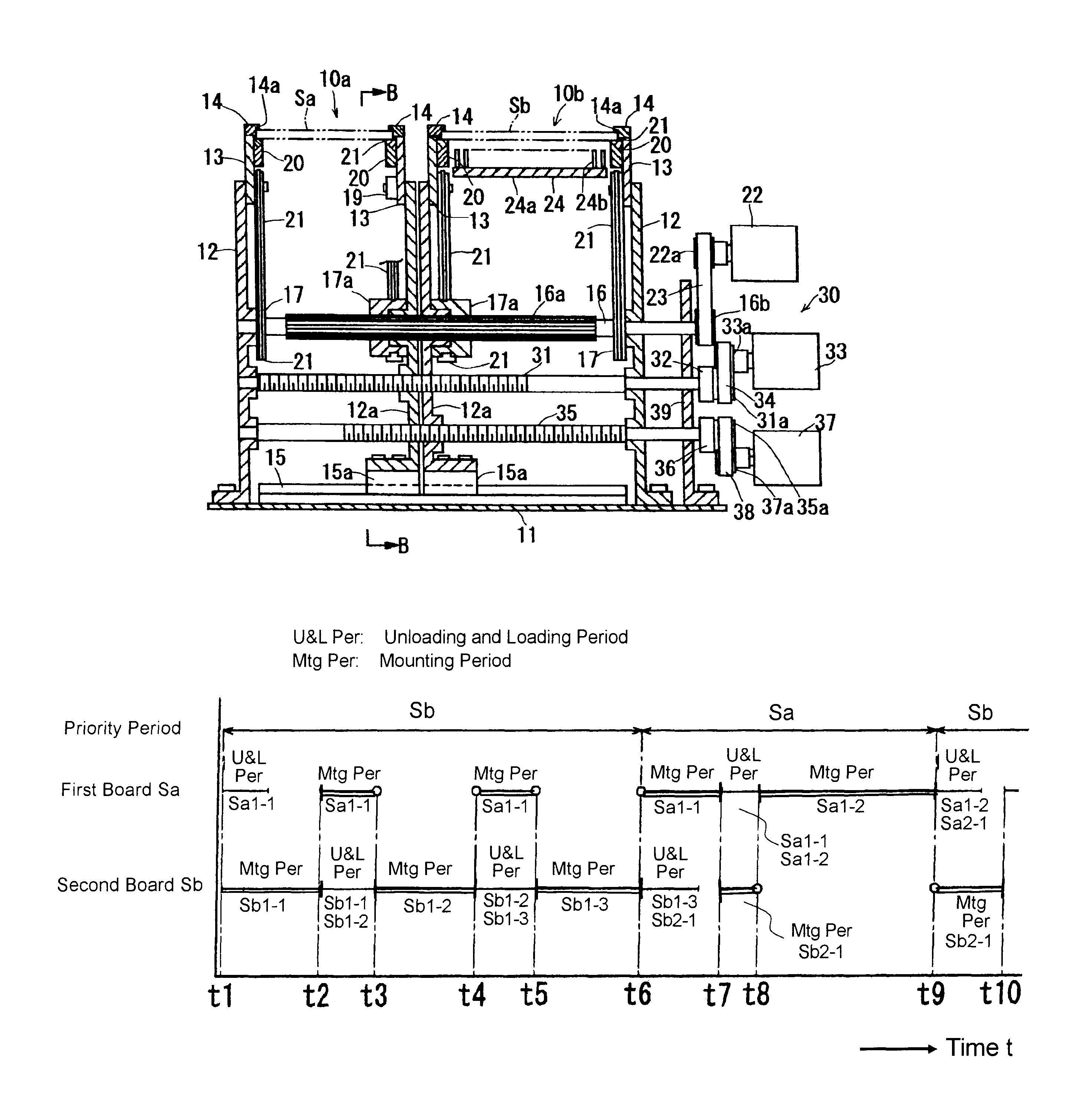
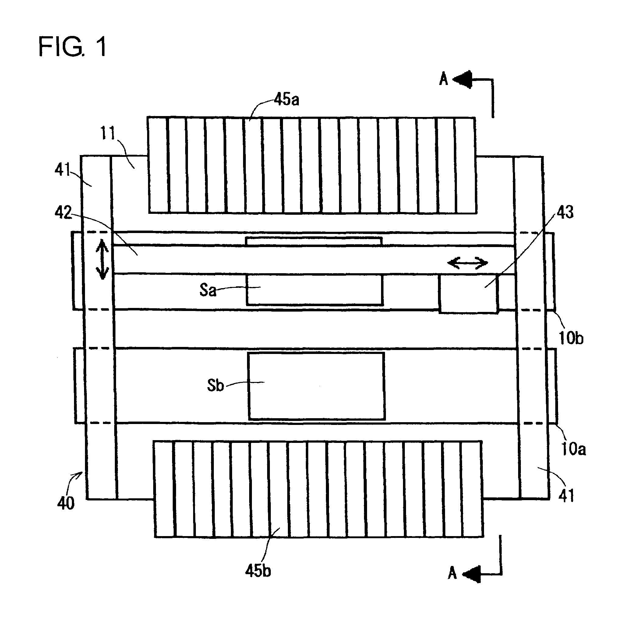
[0022]Hereafter, a component mounting apparatus in one embodiment according to the present invention will be described with reference to the accompanying drawings. Referring now to FIG. 1, the component mounting apparatus is composed of first and second board transfer devices 10a, 10b, conveyor width adjusting devices 30 (FIG. 2) respectively associated with the board transfer devices 10a, 10b, a component placing device 40 and first and second component supply devices 45a, 45b.

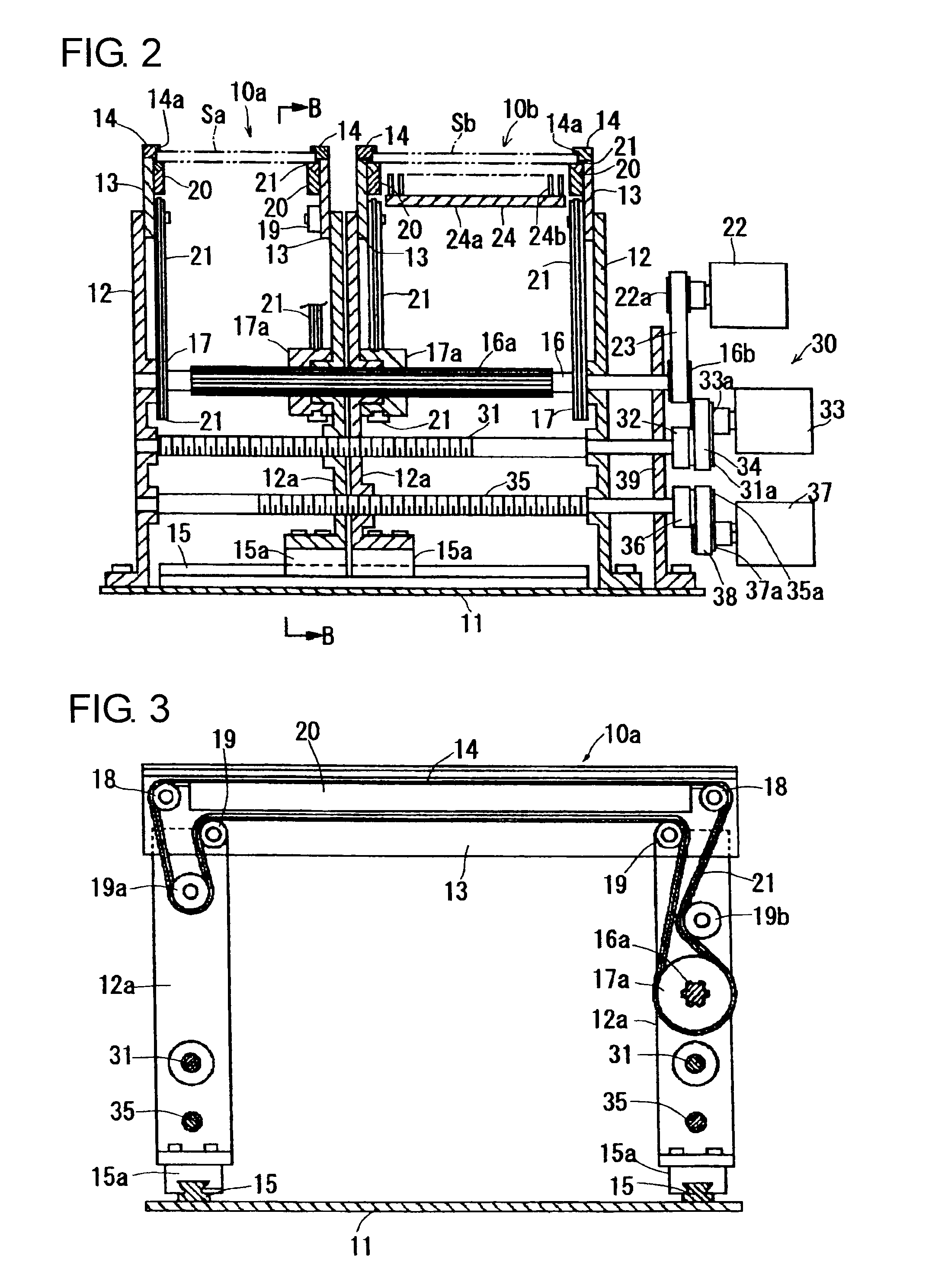
[0023]The first and second board transfer devices 10a. 10b take substantially the same construction with each other, and therefore, the first board transfer device 10a will mainly be described for both of the transfer devices 10a, 10b. In the first board transfer device 10a, as shown in FIGS. 2 and 3, a pair of outside support pedestals 12 are upright fixed on a base 11, and a pair of inside support pedestals 12a which face the outside support pedestals 12, 12 are upright fixed respectively on sliders 15a wh...


PUM

PropertyMeasurementUnit
distanceaaaaaaaaaa
rotationaaaaaaaaaa
constant distanceaaaaaaaaaa

Abstract

In a component mounting apparatus, when one of first and second board transfer devices is performing the unloading and loading of boards, a controller operates a component placing device to mount components on a first or second board loaded by the other board transfer device. Thus, it is possible to effectively utilize the time which is taken for the unloading and the loading of either boards, for component mountings on the other board, so that the efficiency in producing boards can be enhanced. Further, since the controller executes a control so that while component mountings are performed on the first boards of M-sheets on the first board transfer device, component mountings are performed on the second boards of N-sheets on the second board transfer device, it is realized to suppress the occurrence of an intermediate stock of either boards where the first boards of the M-sheets and the second boards of the N-sheets are required.

Description

INCORPORATION BY REFERENCE[0001]This application is based on and claims priority under 35 U.S.C. 119 with respect to Japanese Application No. 2010-166661 filed on Jul. 26, 2010, the entire content of which is incorporated herein by reference.BACKGROUND OF THE INVENTION[0002]1. Field of the Invention[0003]The present invention relates to a component mounting apparatus for mounting components on a board.[0004]2. Discussion of the Related Art[0005]As electronic equipments, there is one in which respective sheets of boards different in kind are combined and arranged in one and the same product. Where components are to be mounted by a component mounting apparatus on such boards, it tends that an intermediate stock of boards in one kind increases due to difference in the combined numbers in sheet of different-kind boards as well as due to difference in the numbers or the like of components to be mounted on the respective kind boards. To avoid this drawback, in JP2008-28262 for example, th...

Claims


Application Information

Patent Timeline
Patent Type & Authority Patents(United States)
IPC IPC(8): H05K13/04
CPCH05K13/08Y10T29/4913Y10T29/53178Y10T29/53091Y10T29/53183Y10T29/53174H05K13/085
Inventor KURODA, HIDEYAYASUI, YOSHIHIROKAWAI, TAKAYOSHIHANEDA, HIROYUKI
Owner FUJI CORP
Why Eureka
Try Eureka