Tower erection system and method

a technology of tower structure and erection system, which is applied in the direction of mechanical equipment, building repairs, machines/engines, etc., can solve the problems of slow and cumbersome system and method of erecting tower structure, the current known crane may not be able to hoist tower elements above the height of approximately 75 meters, and the available cranes and other machinery may not be able to meet the requirements of tower structure height, etc., to achieve the effect of facilitating frame guiding

Inactive Publication Date: 2013-11-19
TINDALL CORP
View PDF21 Cites 15 Cited by
  • Summary
  • Abstract
  • Description
  • Claims
  • Application Information

AI Technical Summary

Benefits of technology

[0012]It is a general object of the present disclosure to provide improved system and method subject matter for erection of tower structures. It is a more specific object of the present disclosure to provide system and method subject matter for erection of tower structures that provides for relatively fast, efficient erection of such tower structures, that allows elements of such tower structures to be placed at relatively high heights, and / or that does not require large forces to lift the various components of such tower structures.
[0016]A self-hoist system according to the present disclosure may, in exemplary embodiments, include one or more hoisting devices, such as winches, as well as cables connected to the hoisting devices and hoist points on a tower section for connection thereto by the cables. A self-hoist system may additionally include guide rollers for engagement with the pilasters to facilitate guiding of the frame.

Problems solved by technology

Many known systems and methods for erecting tower structures are slow and cumbersome, requiring, for example, numerous external cranes or other machinery to lift and position the various elements of the tower structures relative to each other.
Additionally, as tower structures increase in size and height, available cranes and other machinery may not be capable of placing various elements of the tower structures at their required heights.
For example, presently known cranes may not be capable of hoisting tower elements above heights of approximately 75 meters.
Further, the forces required to lift the various elements of a tower structure utilizing currently known systems and methods may be relatively high, due to the weight of the elements and the heights to which the elements must be hoisted.

Method used


Image

  • Tower erection system and method
  • Tower erection system and method
  • Tower erection system and method

Examples


Embodiment Construction

[0041]Reference is presently made in detail to exemplary embodiments of the present subject matter, one or more examples of which are illustrated in or represented by the drawings. Each example is provided by way of explanation of the present subject matter, not limitation of the present subject matter. In fact, it will be apparent to those skilled in the art that various modifications and variations can be made in the present subject matter without departing from the scope or spirit of the present subject matter. For instance, features illustrated or described as part of one embodiment can be used with another embodiment to yield a still further embodiment. Thus, it is intended that the present subject matter covers such modifications and variations as come within the scope of the disclosure and equivalents thereof.

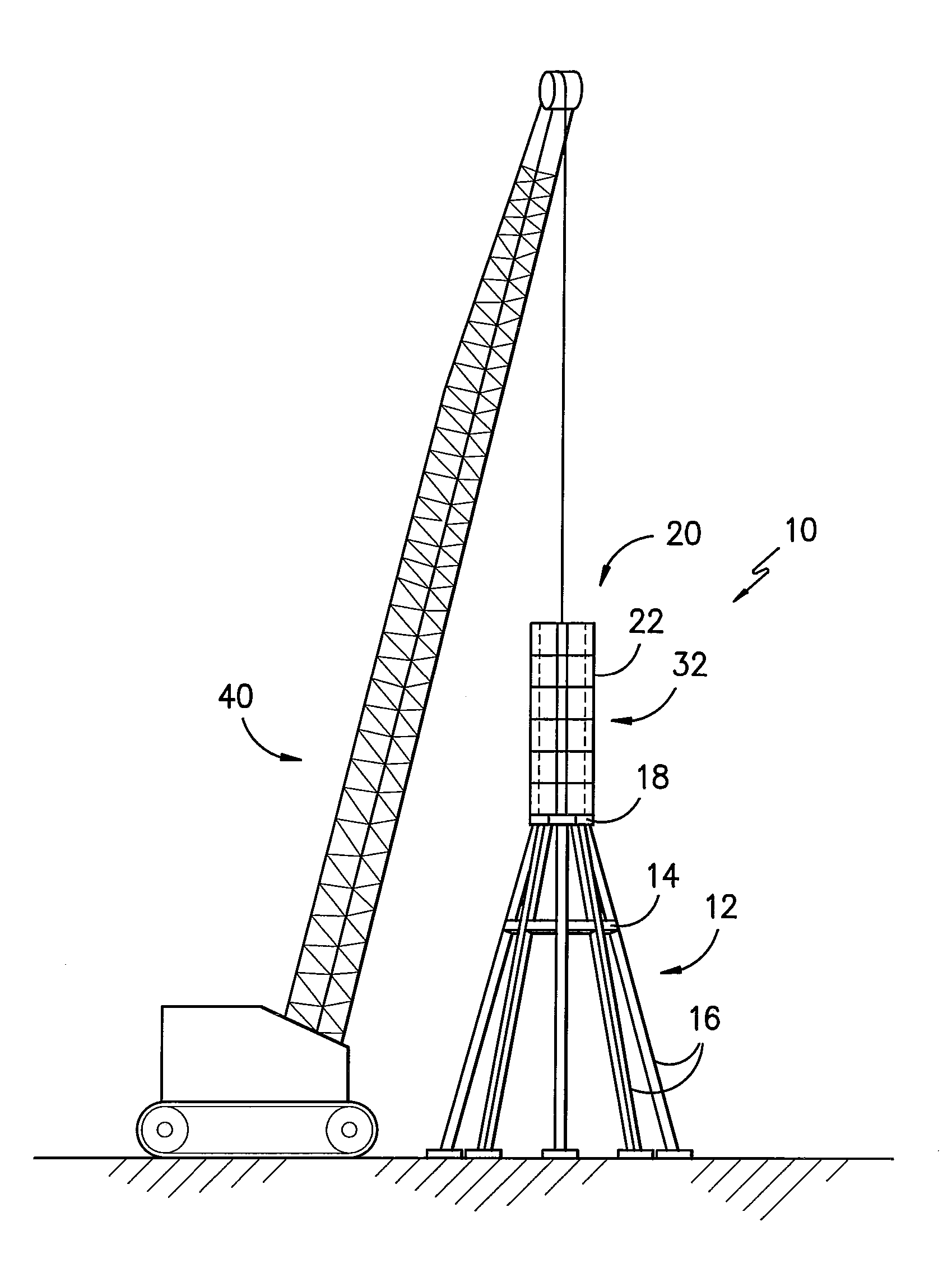
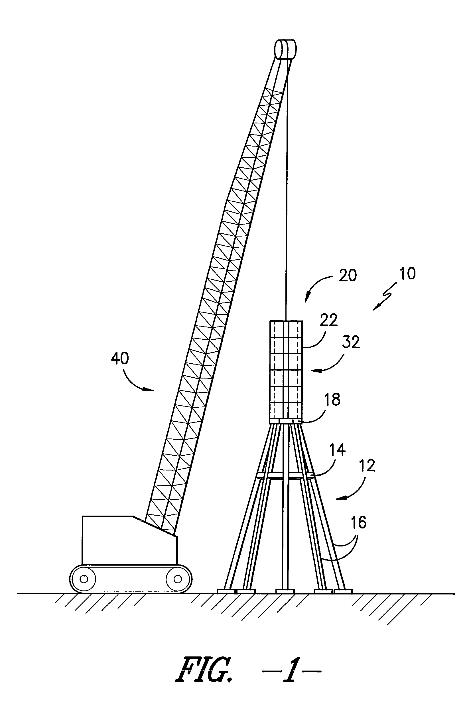
[0042]With reference now to FIG. 1, the tower generally 10 of the present disclosure may include a base portion generally 12. As shown, lateral support structure 14 prov...


PUM


Abstract

Systems and methods are disclosed for erecting a tower. The subject system includes a tower, which may include a base portion and a plurality of tower sections. The subject system may further include a frame provided on the tower, a crane provided on the frame, and a self-hoist system for elevating and lowering the frame relative to the tower. Erection of the tower is facilitated through use of the self-hoist system to elevate the frame, and use of the crane to provide various tower sections on the base portion and an initial tower section or sections.

Description

PRIORITY CLAIM[0001]This application claims the benefit of previously filed U.S. Provisional Patent Application entitled “TOWER ERECTION SYSTEM AND METHOD,” assigned U.S. Ser. No. 61 / 541,303, filed Sep. 30, 2011, and which is incorporated herein by reference for all purposes.FIELD OF THE INVENTION[0002]The present subject matter relates generally to tower structures, and more specifically to systems and methods for erecting tower structures.BACKGROUND OF THE INVENTION[0003]Construction of towers for support of various items has been practiced for many years. Various towers of various materials, including wood, steel, and, more recently, concrete, have been provided to support, for example, electrical transmission lines. In like manner, wind driven apparatus including windmills and wind-driven power generators in various forms and designed for many purposes (including, for example, pumping of water from wells as well as, more recently, generation of electrical power) have also been d...

Claims


Application Information

Patent Timeline
Patent Type & Authority Patents(United States)
IPC IPC(8): E04G21/00
CPCE04H12/344F03D1/001E04H12/00Y02E10/728E04H12/342F03D13/10Y02E10/72E04H2012/006
Inventor ZAVITZ, BRYANT A.LOWNDES, III, WILLIAM
Owner TINDALL CORP
Why Eureka
Try Eureka