Virtual image display device

a virtual image and display device technology, applied in optics, instruments, electrical appliances, etc., can solve the problems of not necessarily perfect see-through, difficult to make an effective pupil diameter, and difficult to make a large display size of virtual images, etc., to achieve stable and highly accurate molding, increase weight reduction or safety, and high quality

Active Publication Date: 2013-11-19
SEIKO EPSON CORP
View PDF16 Cites 245 Cited by
  • Summary
  • Abstract
  • Description
  • Claims
  • Application Information

AI Technical Summary

Benefits of technology

[0011]An advantage of some aspects of the invention is to provide a virtual image display device that enables a see-through observation and can display a virtual image of a high quality by suppressing observation of ghost light.

Problems solved by technology

However, in the device disclosed in JP-A-2006-3879 or the like, the see-through is realized by a pupil division method that uses a light guiding optical system in which an emission opening is smaller than a pupil size, such that it is difficult to make a display size of the virtual image large.
In addition, the light guiding optical system that is smaller than the size of the pupil is used, such that it is difficult to make an effective pupil diameter (a lighting diameter that allows the virtual image to be taken in, and is called an Eyring diameter) large so as to correspond to an individual pupil width in human beings.
In addition, the emission opening or a casing of the light guiding optical system is physically disposed in the vicinity of the pupil, such that a blind spot is generated, and therefore it is not necessarily a perfect see-through.
In this case, a center image and left and right images, which make up the entire image, are necessary to be displayed while these are changed at a time difference by one liquid crystal panel, such that a virtual image display device becomes complex and an observed image becomes dark.
However, it is difficult to display a large image, and in a case where a member such as a see-through prism is connected to the light guiding member, ghost light is generated due to this member and therefore the ghost light easily reaches an eye.
Therefore, it is easy to have a desired angle dependency that is difficult to be realized in a single layer, with respect to the reflectance of a reflective film.

Method used


Image

  • Virtual image display device
  • Virtual image display device
  • Virtual image display device

Examples


Embodiment Construction

[0041]Hereinafter, a virtual image display device related to one embodiment of the invention will be described in detail with reference to the accompanying drawings.

A. External Appearance of Virtual Image Display Device

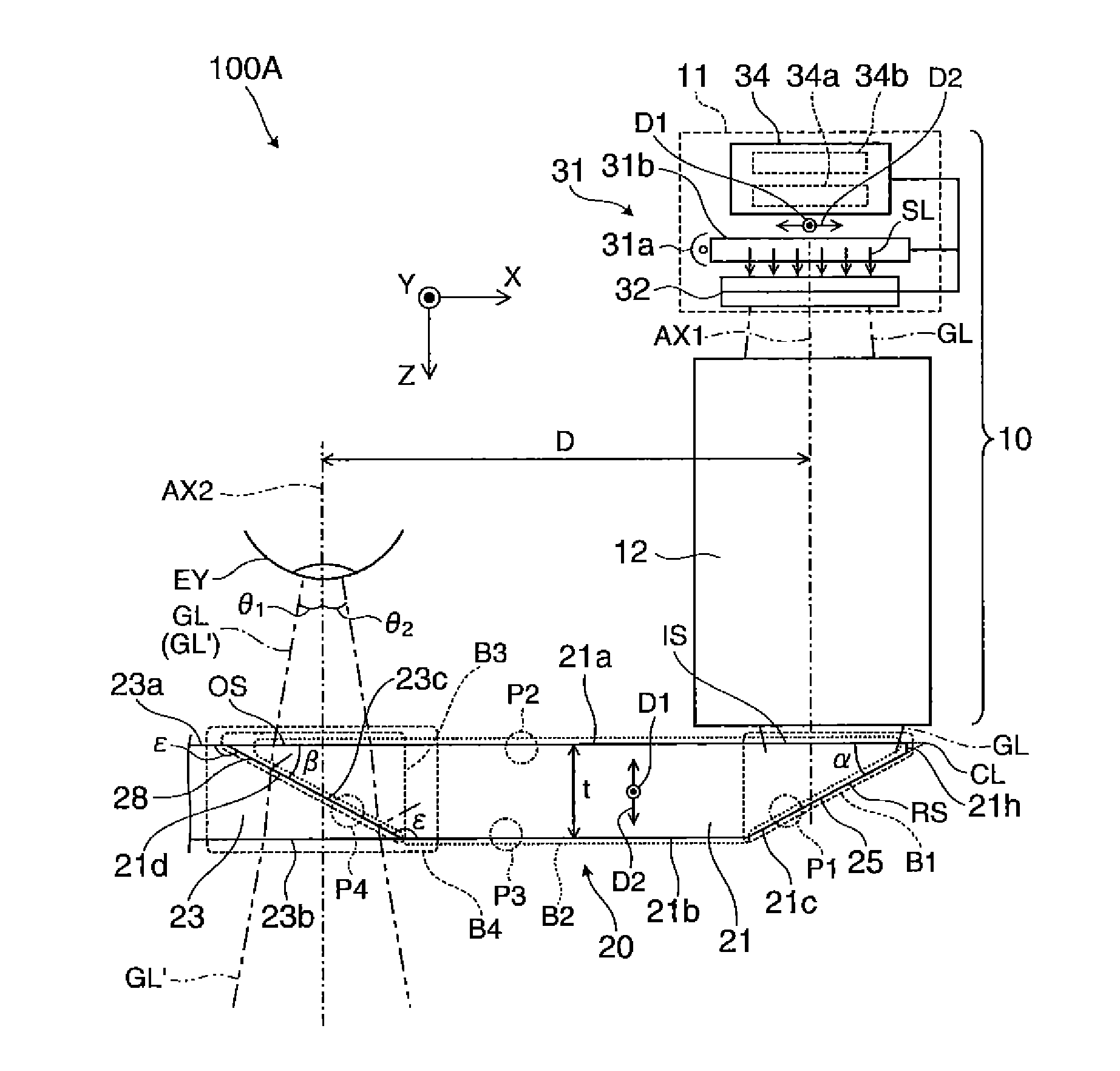
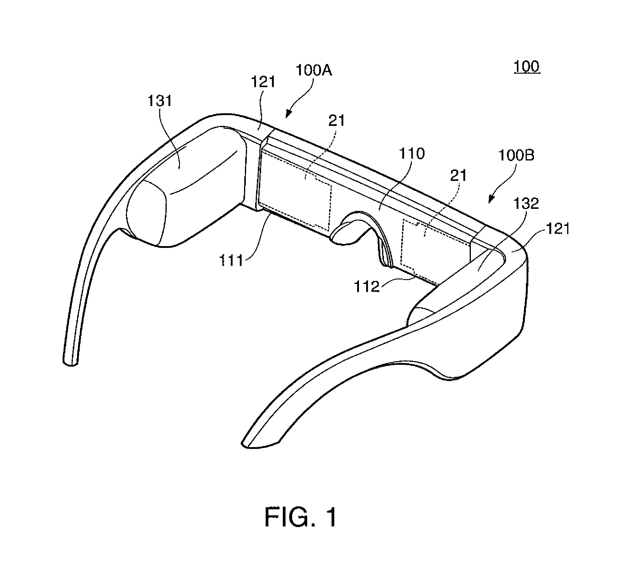
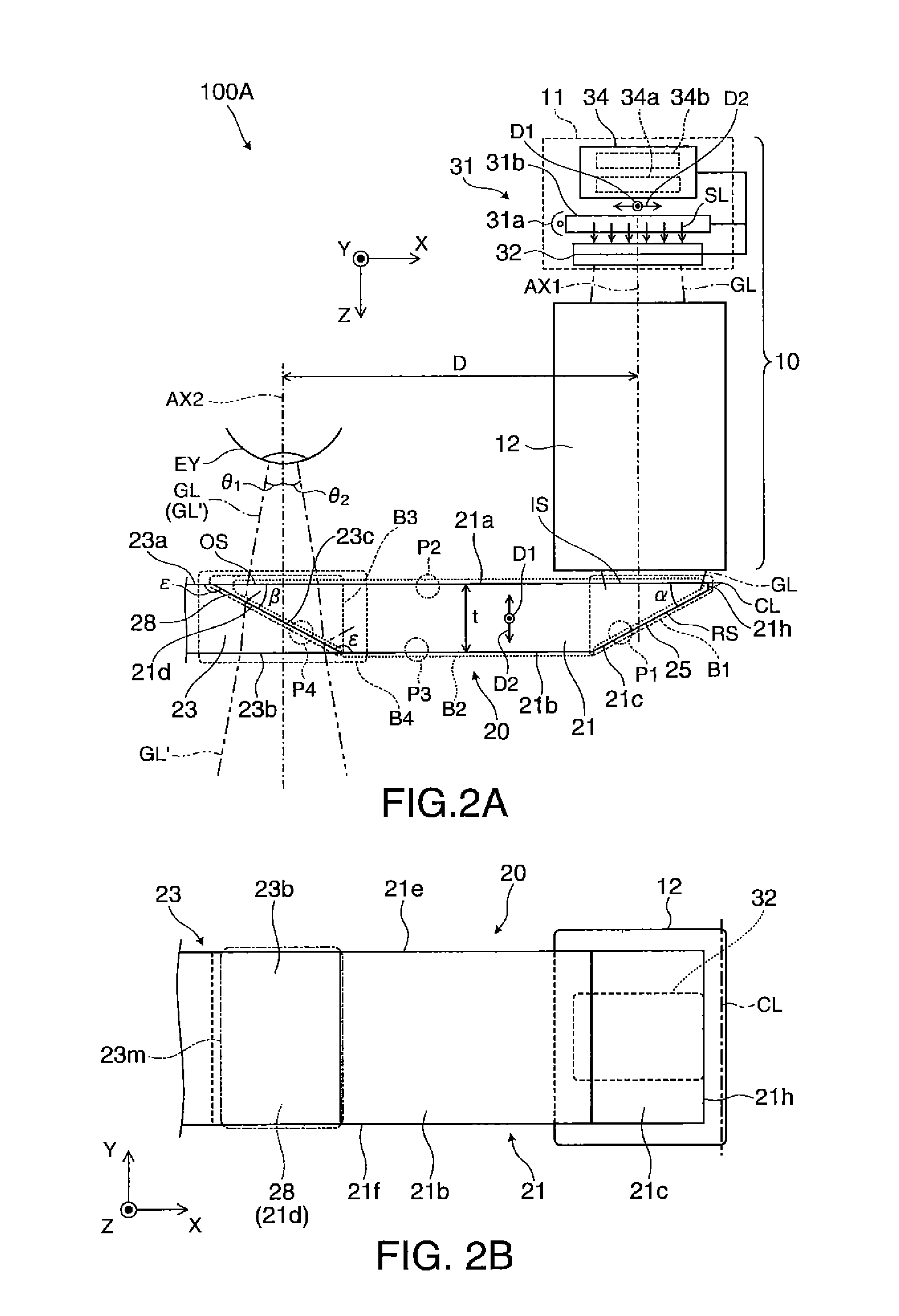
[0042]A virtual image display device 100 of an embodiment illustrated in FIG. 1 is a head-mounted display having the same external appearance as eyeglasses, and allows an observer wearing this virtual image display device 100 to perceive image light via a virtual image and allows the observer to observe an external image via a see-through. The virtual image display device 100 includes an optical panel 110 that covers the front of the observer's eyes, a frame 121 that maintains the optical panel 110, and first and second driving portions 131 and 132 that are provided at a portion ranging from arm to temple of the frame 121. Here, the optical panel 110 includes a first panel portion 111 and a second panel portion 112, and the both panel portions 111 and 112 are formed o...


PUM


Abstract

A half mirror layer has an angle dependency in which when an angle of incidence becomes larger than the angle of incidence range of image light, reflectance increases, such that it is possible to prevent unintended light, which is emitted to a light transmitting member from a light guiding member and is reflected inside a light transmitting member, from being returned to a light emission portion of the light guiding member after passing through the half mirror layer as a reflective film at a relatively large angle of incidence. Therefore, it is possible to prevent the image light passed through the light transmitting member from becoming ghost light while mitigating the demand for increasing processing accuracy of the light transmitting member, and bonding accuracy between the light guiding member and the light transmitting member.

Description

[0001]This application claims priority to JP 2011-022443 filed in Japan on Feb. 4, 2011, the entire disclosure of which is herein incorporated by reference in its entirety.BACKGROUND[0002]1. Technical Field[0003]The present invention relates to a virtual image display device such as a head-mounted display that is used by being mounted on the head.[0004]2. Related Art[0005]In recent years, as a virtual image display device that allows a virtual image to be formed and to be observed similarly to the head-mounted display, various virtual image display devices of a type in which image light from a display element is guided to a pupil of an observer by a light guiding plate have been suggested.[0006]In this virtual image display device, the image light and external light overlap with each other, such that a see-through optical system has been suggested (refer to JP-A-2006-3879 and JP-A-2010-224473).[0007]However, in the device disclosed in JP-A-2006-3879 or the like, the see-through is r...

Claims


Application Information

Patent Timeline
Patent Type & Authority Patents(United States)
IPC IPC(8): G02B27/14
CPCG02B27/0172H04N13/0011H04N13/0429G02B6/00G02B2027/0125G02B6/0045G02B2027/0178G02B2027/0112G02B2027/0118G02B2027/0123H04N13/111H04N13/332H04N13/344
Inventor TOTANI, TAKAHIROTAKAGI, MASAYUKIMIYAO, TOSHIAKIKOMATSU, AKIRATAKEDA, TAKASHI
Owner SEIKO EPSON CORP
Why Eureka
Try Eureka