
Apparatus for modifying electron beam aspect ratio for X-ray generation

an electron beam and aspect ratio technology, applied in the field of electron emitters, can solve the problems of large cathode aspect ratio, difficult to design good beam optics, and difficulty in beam optics design

Active Publication Date: 2013-11-19
GENERAL ELECTRIC CO
View PDF21 Cites 34 Cited by
  • Summary
  • Abstract
  • Description
  • Claims
  • Application Information

AI Technical Summary

Problems solved by technology

The drawback of using such large aspect ratio cathodes is its difficulty of beam optics design.
That is, with the generation of an electron beam with a large aspect ratio (by a similarly shaped cathode), it is very difficult to design good beam optics, which are required to achieve a small focal spot on the target.
Additionally, with specific reference to x-ray tubes that implement a thermionic cathode, the large aspect ratio of the cathode imposes additional problems.
For a large aspect ratio thermionic cathode, there is a larger edge area, which results in a temperature of the cathode that tends to be less uniform than a circular cathode.

Method used


Image

  • Apparatus for modifying electron beam aspect ratio for X-ray generation
  • Apparatus for modifying electron beam aspect ratio for X-ray generation
  • Apparatus for modifying electron beam aspect ratio for X-ray generation

Examples


Embodiment Construction

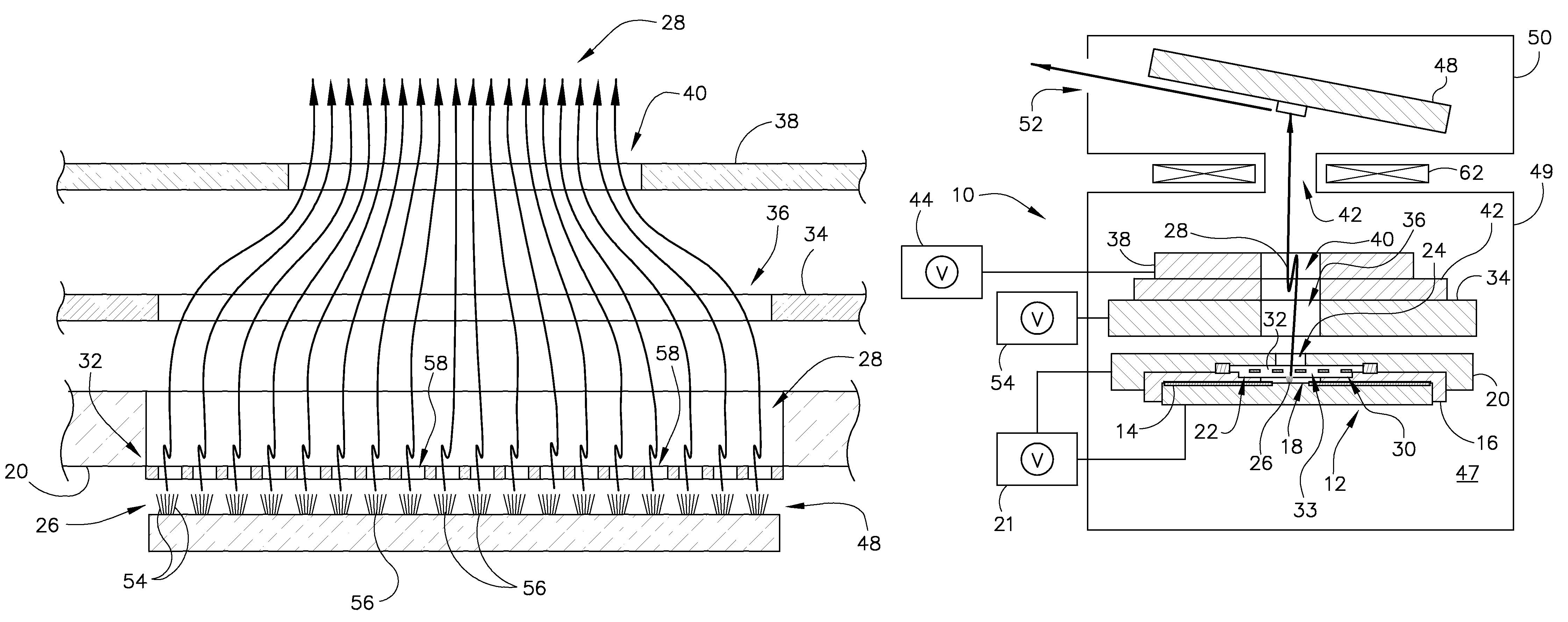
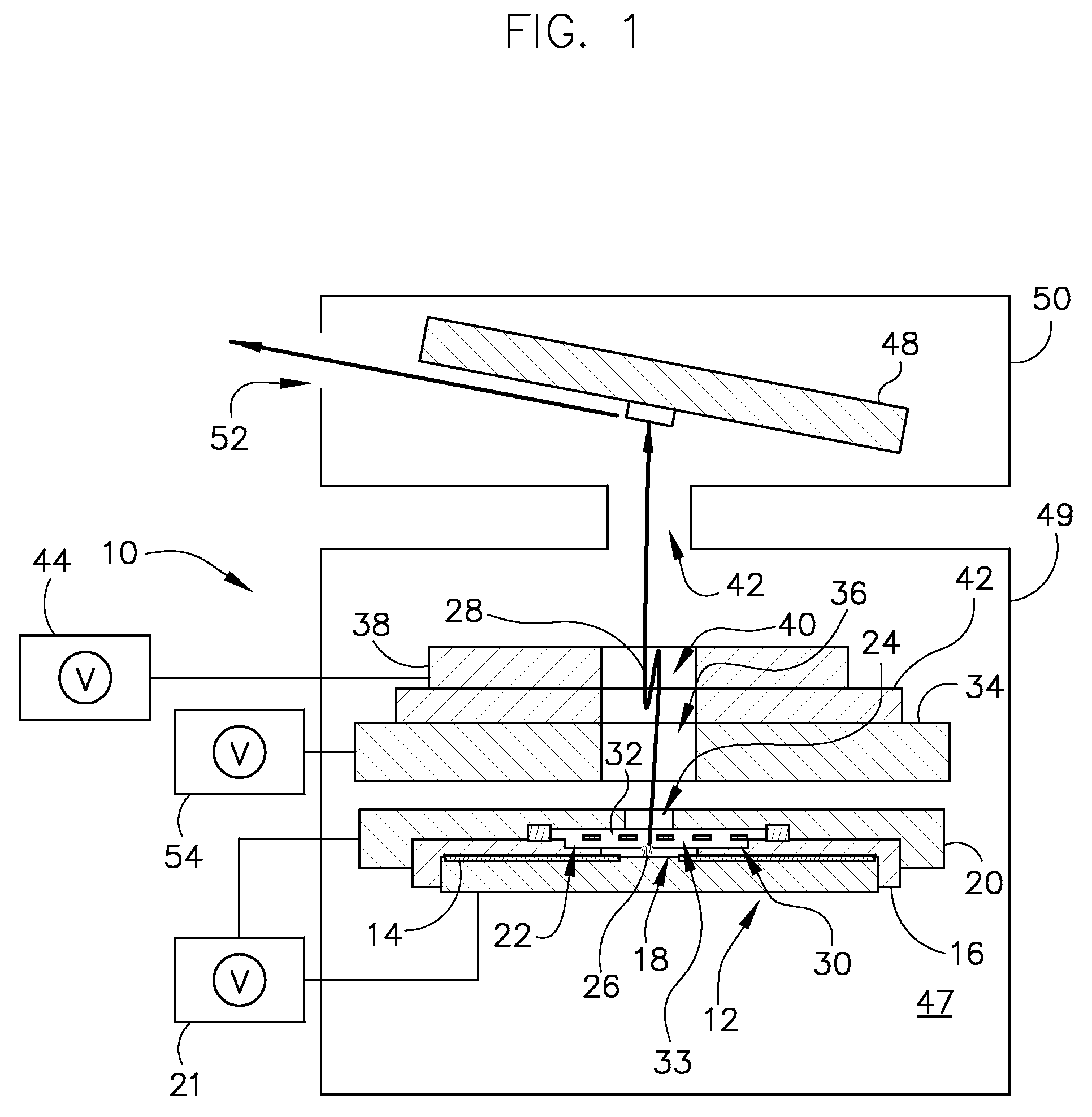
[0027]The operating environment of embodiments of the invention is described with respect to an electron generator unit and x-ray source that includes a field emitter based cathode. That is, the electron beam emission and electron beam focusing and reshaping schemes of the invention are described as being provided for an electron generator unit and field emitter based x-ray source. However, it will be appreciated by those skilled in the art that embodiments of the invention for such electron beam emission and electron beam focusing and reshaping schemes are equally applicable for use with other cathode technologies, such as dispenser cathodes and other thermionic cathodes. The invention will be described with respect to a field emitter unit, but is equally applicable with other cold cathode and / or thermionic cathode structures.

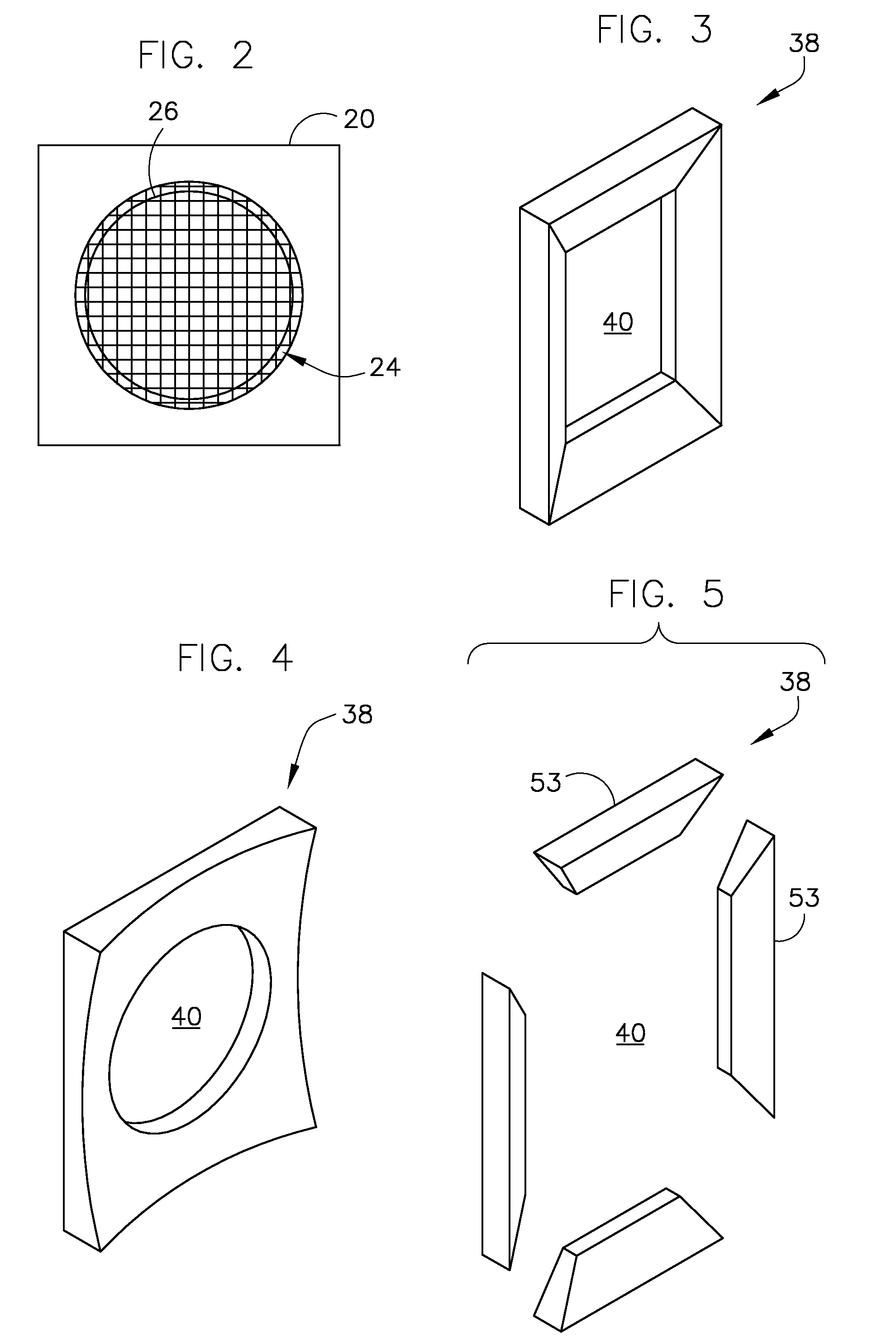
[0028]Referring to FIG. 1, a cross-sectional view of an electron generator unit 10 (i.e., cathode assembly) is depicted according to one embodiment of the inv...


PUM


Abstract

An apparatus for modifying an aspect ratio of an electron beam to form a focal spot having a desired size and aspect ratio on a target anode is disclosed. The apparatus includes an emitter element configured to generate an electron beam having a first aspect ratio shape and an extraction electrode positioned adjacent to the emitter element to extract the electron beam out therefrom, the extraction electrode including an opening therethrough. The apparatus also includes at least one shaping electrode positioned to receive the electron beam after passing through the extraction electrode, the shaping electrode defining a non-circular aperture therein and being configured to provide at least one of shaping and focusing of the electron beam to have a second aspect ratio shape different from the first aspect ratio shape so as to form a focal spot having a desired size and aspect ratio on a target anode.

Description

BACKGROUND OF THE INVENTION[0001]The present invention relates generally to electron emitters, and, more particularly, to an apparatus for modifying an aspect ratio of an electron beam to form a focal spot having a desired size and aspect ratio on a target anode.[0002]In an x-ray imaging system, formation of a small focal spot on a target anode is desired to achieve high-quality x-ray imaging. In order to maximize the target thermal management and cathode emission capability, an x-ray tube is configured such that a non-circular (i.e., linear) focal spot is formed on the target. In the imaging system, the detector will view the x-ray spot at a shallow angle (7-12 degree) to achieve an effective small optical spot size.[0003]To achieve a linear focal spot, today's x-ray tubes use a linear electron emitter element or cathode that has almost the same aspect ratio as the desired focal spot, and a focusing cup / electrode is used to focus the electron beam onto the target anode. The drawbac...

Claims


Application Information

Patent Timeline
Patent Type & Authority Patents(United States)
IPC IPC(8): H05G1/52
CPCH01J35/065H01J35/14H01J2235/02H01J2235/062H01J2235/068H01J35/147
Inventor ZOU, YUNZAVODSZKY, PETER ANDRASVERMILYEA, MARK E.LEMAITRE, SERGIOFRONTERA, MARK ALAN
Owner GENERAL ELECTRIC CO
Learn More