Enclosure for small animals during awake animal imaging

Active Publication Date: 2013-11-26
UT BATTELLE LLC
View PDF19 Cites 10 Cited by
  • Summary
  • Abstract
  • Description
  • Claims
  • Application Information

AI Technical Summary

Benefits of technology

[0012]Disclosed are several examples of enclosures for restraining an animal during a medical imaging procedure. The enclosures include a tubular body made of a radiolucent material and a separate window made of an optically clear material that is affixed to the body. The wi

Problems solved by technology

Motion of a living subject during medical imaging procedures can cause image artifacts.
In some cases, motion artifacts degrade the diagnostic value of an image, wasting significant time and money.
Unrestrained awake animals tend to move around rapidly and present imaging challenges.
Although sedation and physical restrain

Method used


Image

  • Enclosure for small animals during awake animal imaging
  • Enclosure for small animals during awake animal imaging
  • Enclosure for small animals during awake animal imaging

Examples


Embodiment Construction

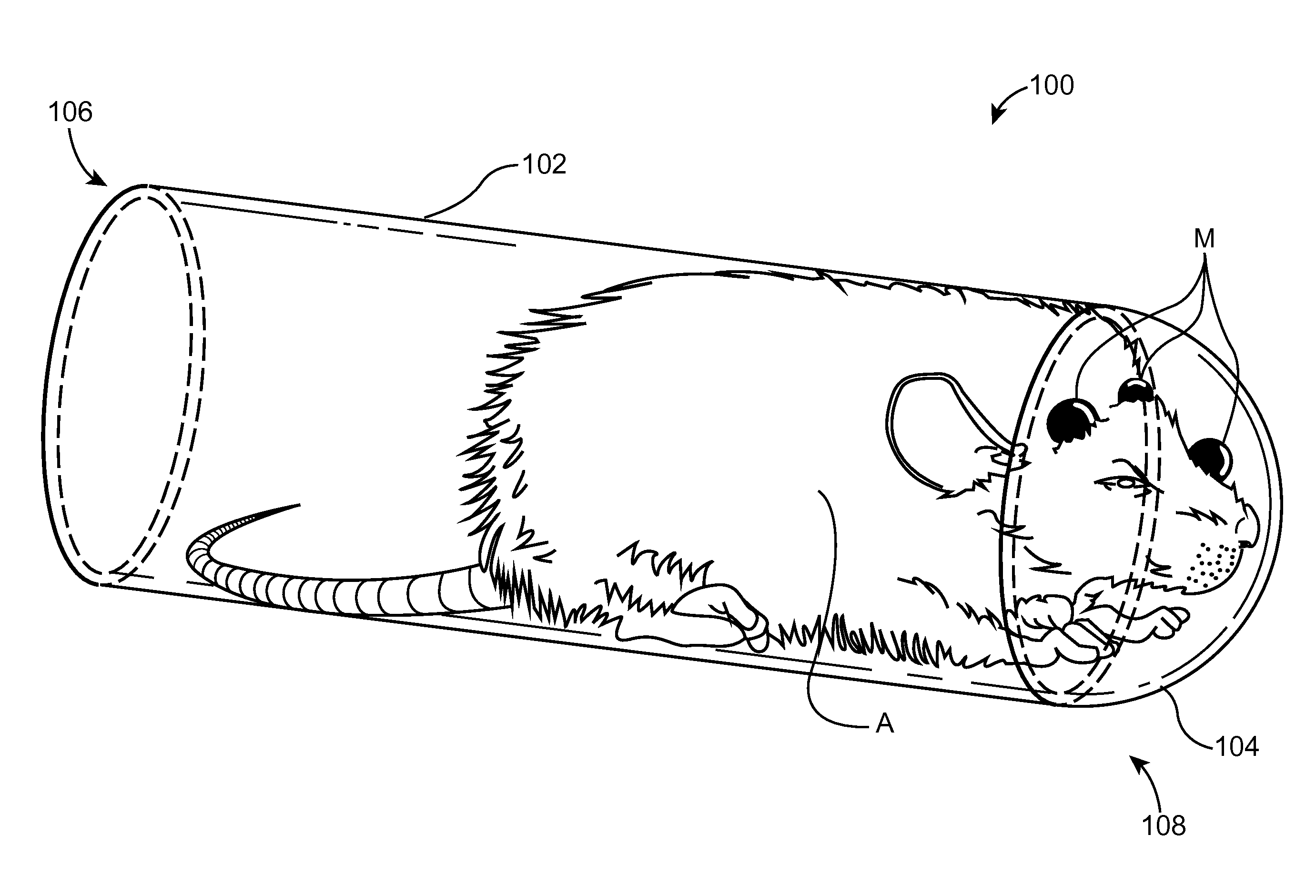
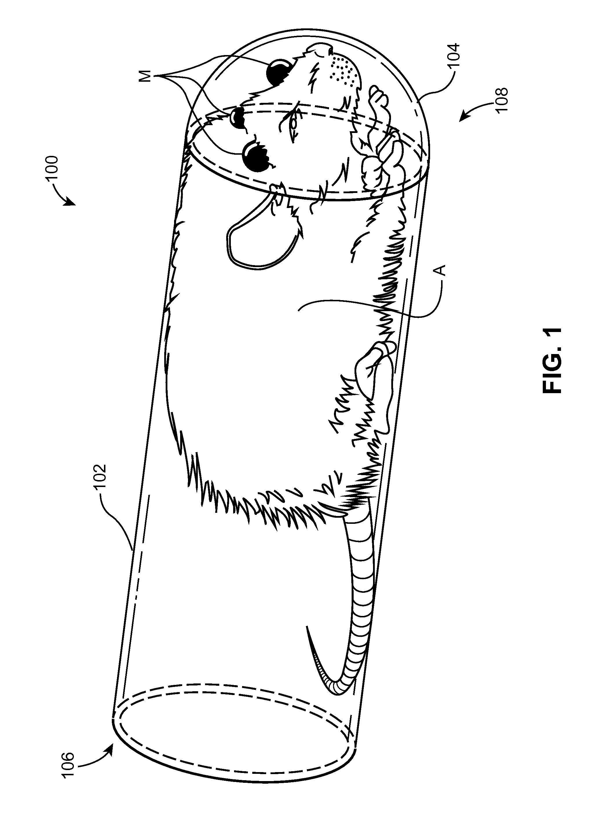
[0019]Referring first to FIGS. 1-3, an enclosure 100 restrains an awake animal (A), such as a rat or a mouse, during a medical imaging procedure. In order to correct the images for the 3D motion of the awake animal (A), two cameras are used to capture the positions of the artificial markers (M) affixed to the animal (A), which are illuminated by infrared light emitting diodes (LEDs) as described in the incorporated references. The imaging procedure and motion correction equipment and methods are fully described in the incorporated references and a full description will not be included here for brevity. In the example of FIG. 1, the enclosure 100 includes a body 102 and a viewing window 104 that is a separate and detachable element from the body 102.

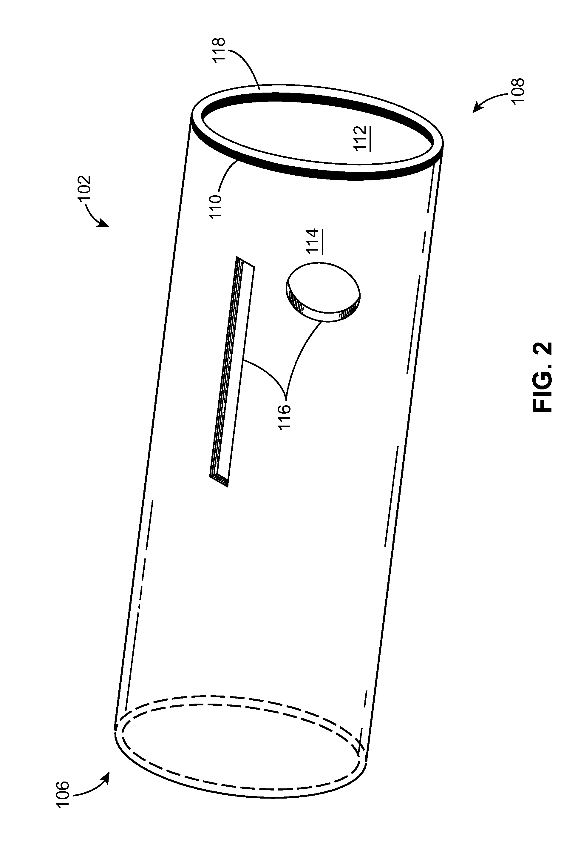
[0020]The body 102 is a tubular structure, defining an interior volume for accepting the animal (A), and having a cross sectional shape that is preferably circular (shown). Shapes such as square, rectangular, triangular, elliptical, or so...


PUM


Abstract

An enclosure or burrow restrains an awake animal during an imaging procedure. A tubular body, made from a radiolucent material that does not attenuate x-rays or gamma rays, accepts an awake animal. A proximal end of the body includes an attachment surface that corresponds to an attachment surface of an optically transparent and optically uniform window. An anti-reflective coating may be applied to an inner surface, an outer surface, or both surfaces of the window. Since the window is a separate element of the enclosure and it is not integrally formed as part of the body, it can be made with optically uniform thickness properties for improved motion tracking of markers on the animal with a camera during the imaging procedure. The motion tracking information is then used to compensate for animal movement in the image.

Description

STATEMENT REGARDING FEDERALLY SPONSORED RESEARCH AND DEVELOPMENT[0001]This invention was made with government support under Contract No. DE-AC05-00OR22725 awarded by the U.S. Department of Energy. The government has certain rights in the invention.CROSS-REFERENCE TO RELATED APPLICATIONS[0002]The present application relates to U.S. Pat. No. 8,170,302 “System and Method for Generating Motion Corrected Tomographic Images”, and United States Patent Application Publication Number 2008 / 0317313 “System and Method for Tracking Motion for Generating Motion Corrected Tomographic Images”, with each being incorporated herein by reference as if included at length.THE NAMES OF THE PARTIES TO A JOINT RESEARCH AGREEMENT[0003]None.BACKGROUND OF THE INVENTION[0004]1. Field of the Invention[0005]The present disclosure relates to medical imaging of small animals and more specifically to an enclosure for accommodating small animals while being imaged in an awake state.[0006]2. Description of the Related...

Claims


Application Information

Patent Timeline
IPC IPC(8): A01K29/00
CPCA01K1/031A01K1/0613A61D3/00A61B6/04A61B6/527
Inventor GODDARD, JR., JAMES S.
Owner UT BATTELLE LLC
Why Eureka
Try Eureka