
Provided in a liquid dispenser

a technology of liquid dispensers and liquids, applied in the direction of liquid dispensers, lighting and heating apparatus, containers, etc., can solve the problems of excessive wear, light entails an increase in electric power consumption, and the suspension system is subject to a possible breakage, so as to avoid an inadequate filling of the container

Active Publication Date: 2013-11-26
ELECTROLUX DO BRASIL
View PDF5 Cites 3 Cited by
  • Summary
  • Abstract
  • Description
  • Claims
  • Application Information

AI Technical Summary

Benefits of technology

The present invention aims to prevent the container from being too little filled with liquid due to lack of lighting. The dispenser includes a lighting means that not only lights up the inside of the dispenser but also provides an external signal to help users find it easily, without needing to switch on the main lighting in the room. This makes the dispenser more user-friendly and convenient to locate, especially in environments with poor lighting or no lighting at all.

Problems solved by technology

One of the disadvantages associated with this dispenser resides in the fact of the same being directly exposed to the environment, thereby facilitating the ingress of dirt and / or microorganisms, and therefore requiring periodic cleaning thereof.
As such, it is subjected to vertical strains arising from the provision of support to objects or to human support, being thereby subjected to a possible breakage of the suspension system and excessive wear of the elements that make up the same.
Thus, when the control is performed by the user by pressing a button or equivalent means, the poor visibility of the surface of the liquid in these conditions might lead the user to interrupt the dispensing of liquid before the proper time, or otherwise that same poor visibility might lead such user to keep the activating button pressed until the capacity of the container is exceeded, with the consequent occurrence of spilling.
However, such switching on of the lights entails an increase in electric power consumption, in addition to requiring an increased attention on the part of the user, who must not forget to turn off the light when leaving the room.

Method used


Image

  • Provided in a liquid dispenser
  • Provided in a liquid dispenser
  • Provided in a liquid dispenser

Examples


Embodiment Construction

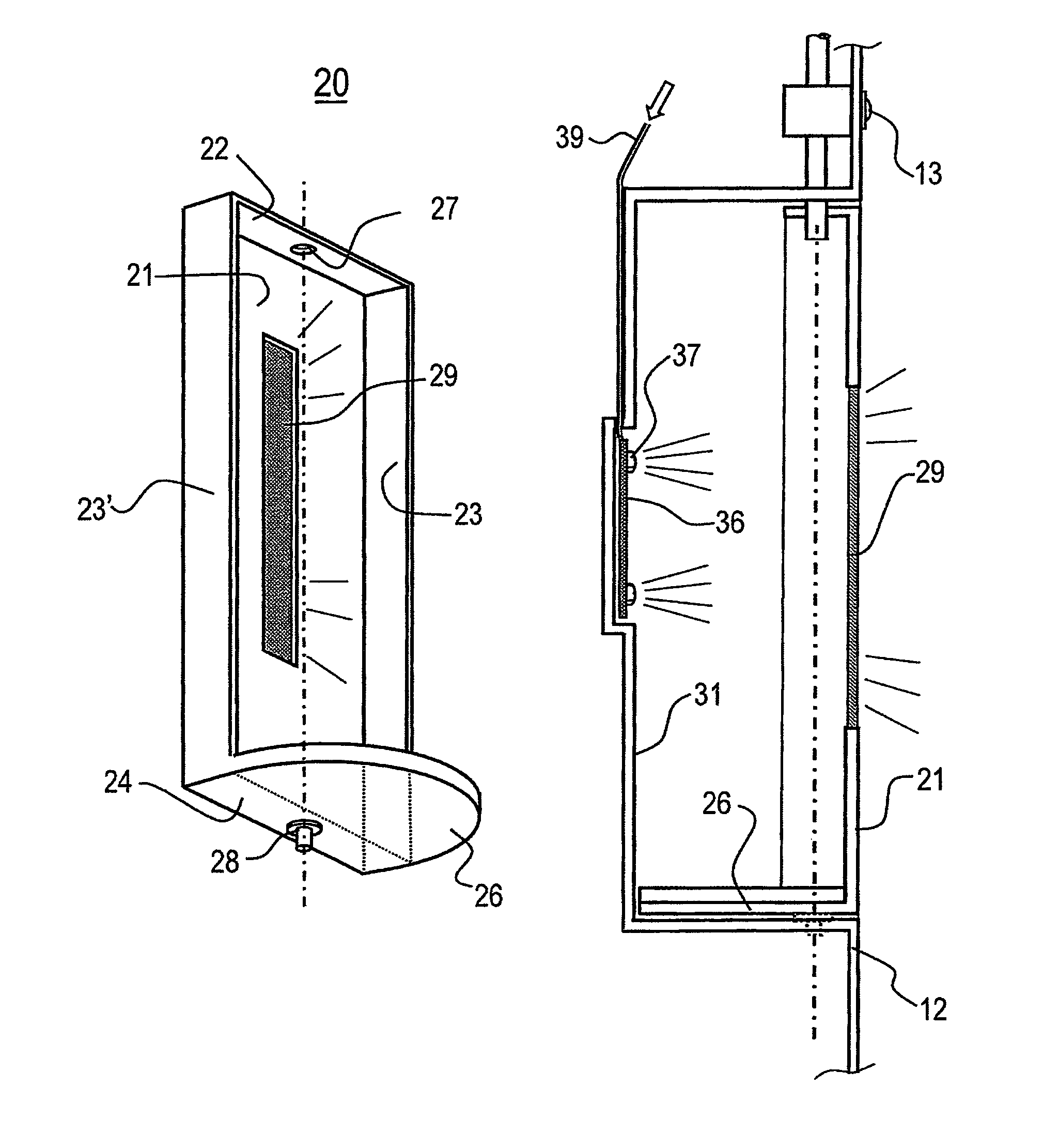
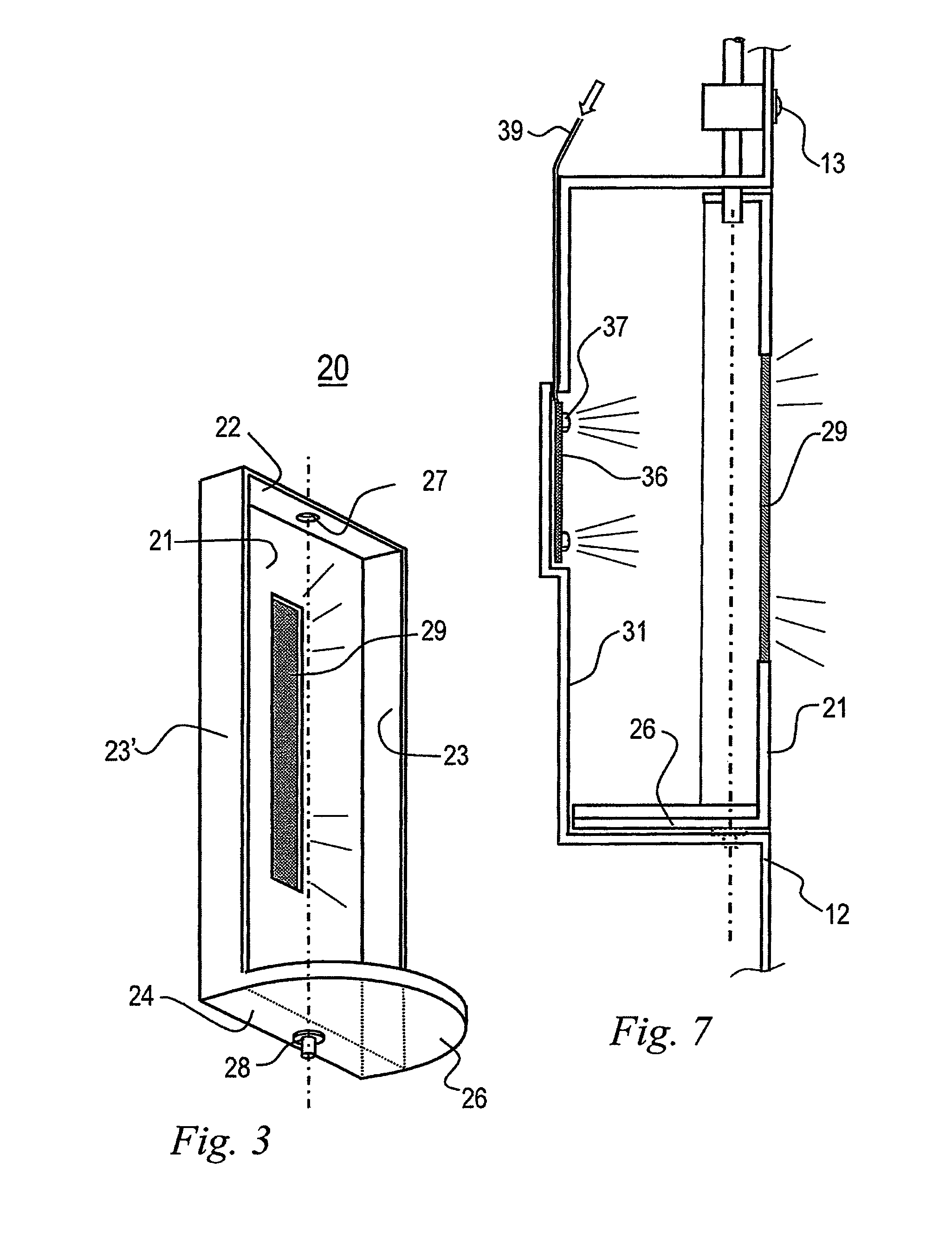
[0025]Now referring to FIG. 3, the dispenser comprises a rotary assembly 20 in the shape of a parallelepiped box of shallow depth, comprising a larger vertical panel 21, two vertical panels 23 and 23′ and two horizontal panels, an upper horizontal panel 22 and a lower horizontal panel 24, the latter being provided with an extension in the shape of a semi-circular flap 26. The assembly formed by panels 21, 22, 23, 23′ and 24 with its flap 26 constitutes the niche wherein is accommodated the container intended to be filled with the liquid. The upper horizontal panel 22 is provided at the center thereof with a through hole 27 through which is projected the liquid supply tube when this assembly is mounted on the refrigerator door. The lower horizontal panel is provided at the center thereof with a supporting pin 28, which together with the hole 27 defines the vertical axis of rotation of the rotary assembly 20. Further according to the invention, the larger panel 21 is provided, along t...


PUM


Abstract

An improvement in a liquids dispensing means comprising a niche for accommodating a container to be filled with liquid, the niche being associated with the outer panel (12) of a cabinet, being lighted from the rear wall thereof (21, 56), a part of the light flux impinging on a window provided with a sheet of translucent material (29) located in the closing means (21, 51) of the niche, the window being in substantial alignment / register with the lighting means (36, 37, 54) provided on the rear wall.

Description

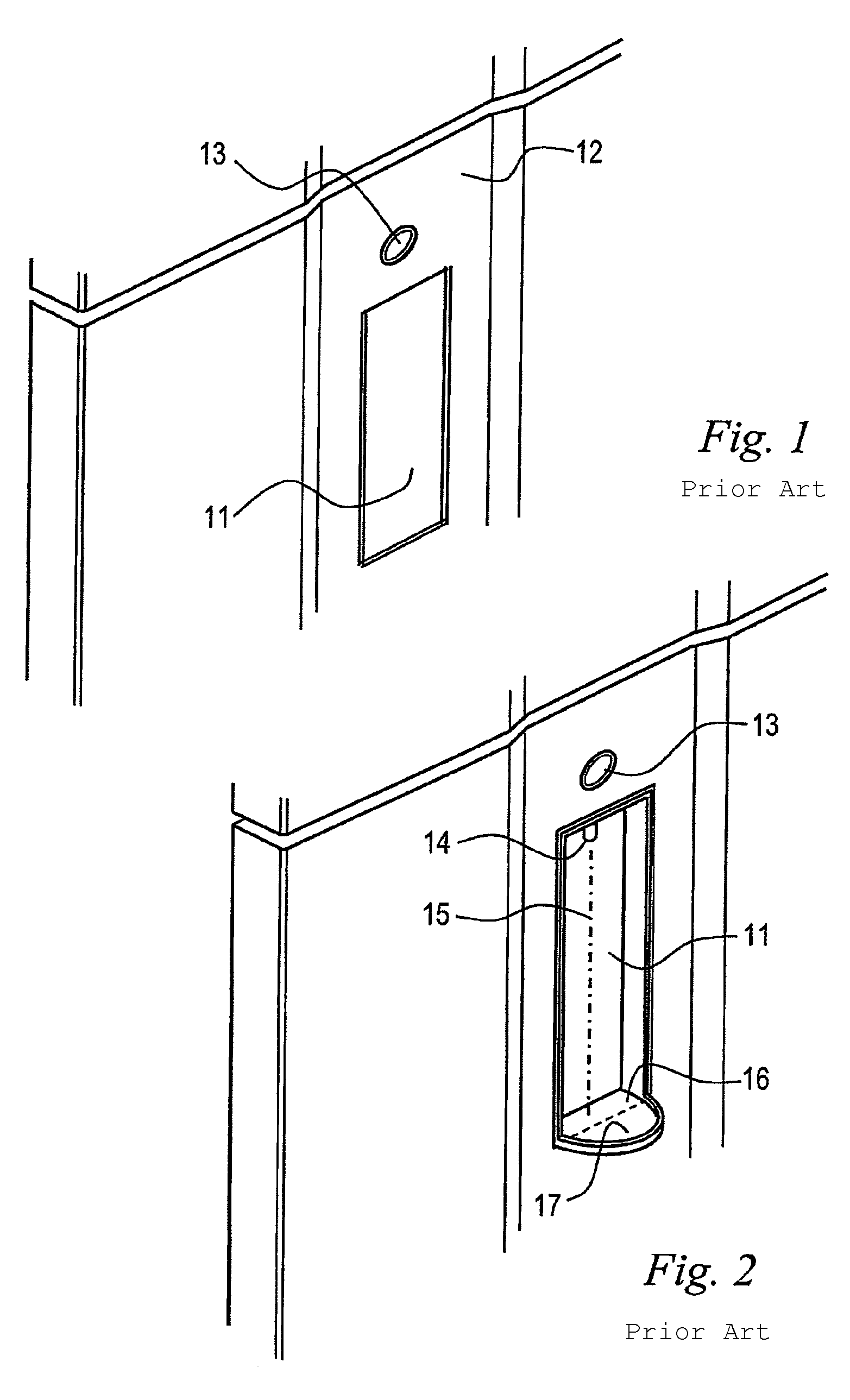
FIELD OF THE INVENTION[0001]The present invention relates to an improvement provided in liquid dispensers, and more particularly to the water dispensers located in niches accessible from the outside of refrigerator cabinets.DESCRIPTION OF THE PRIOR ART[0002]Currently, a large number of refrigerators are equipped with iced water or ice dispensers that may be used by the users without requiring the opening of the main door of the refrigerator. In addition to the advantage of a more comfortable use, such dispensers provide a reduction in electric power consumption, since the opening of the door would cause the loss of a substantial amount of cold air from the refrigerated cabinet, thereby requiring the activation of the compressor to return the temperature within the cabinet to its normal values. The said dispensers are normally located on the front door of the cabinets and are configured in the form of niches or recesses in which are inserted or supported the containers or drinking gl...

Claims


Application Information

Patent Timeline
Patent Type & Authority Patents(United States)
IPC IPC(8): B65D5/66
CPCB67D1/0003B67D1/0857B67D1/0875F25D23/126F25D27/00F25D2327/001F25D2323/023F25D2700/04F25D25/00
Inventor FILHO, MARIO GNYPEKMIRANDA, JACQUES E.WOLFF, RODRIGO TELLESCHRESTENZEN, LIZANDROFILHO, LUIS FERNANDO ZENIDAVIN, ADRIANO
Owner ELECTROLUX DO BRASIL
Learn More