Utility panel for a dispenser

a technology for utility panels and dispensers, applied in the field of dispensers, can solve the problems of providing a system and losing the opportunity to communicate such messages with the users of the dispensers

Inactive Publication Date: 2013-11-26
GOJO IND INC
View PDF19 Cites 8 Cited by
  • Summary
  • Abstract
  • Description
  • Claims
  • Application Information

AI Technical Summary

Benefits of technology

[0040]It will, therefore, be appreciated that one advantage of one or more embodiments of the present invention is that a utility panel for a wall-mounted dispenser is easily retrofit thereto without the need for tools. Another advantage of the present invention is that the utility panel for a wall-mounted dispenser provides a viewing window to allow indicia to be removably installed in a window for viewing by users of the dispenser. Still another advantage of the present invention is that the utility panel may be attached to a backplate that is configured to be attached to any desired surface. Yet another advantage of the present invention is that various utility panels having specific functions may be interchangeably attached to the backplate.

Problems solved by technology

Unfortunately, existing dispensers fail to provide a system in which advertisements or other informational content can be provided, and as such, opportunities to communicate such messages with the users of the dispensers are lost.
And while existing dispensers can be replaced with new dispensers that can display informational content, such an endeavor is generally cost-prohibitive and results in waste.

Method used


Image

  • Utility panel for a dispenser
  • Utility panel for a dispenser
  • Utility panel for a dispenser

Examples


Embodiment Construction

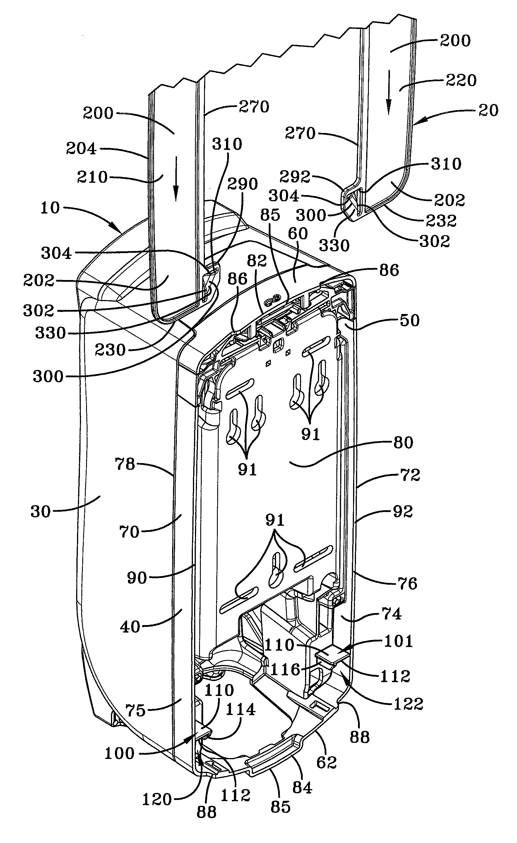
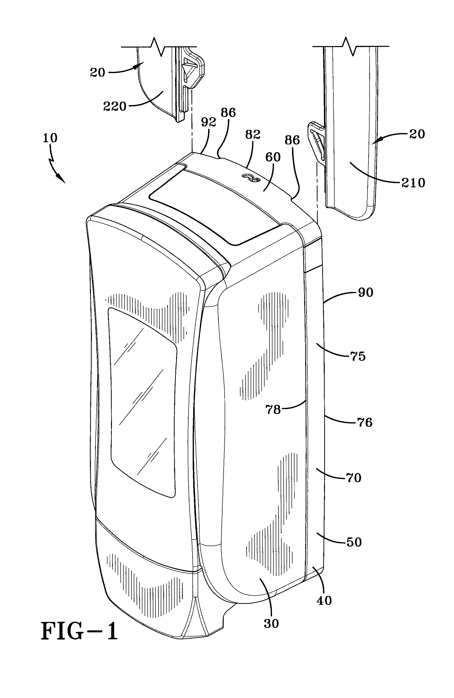
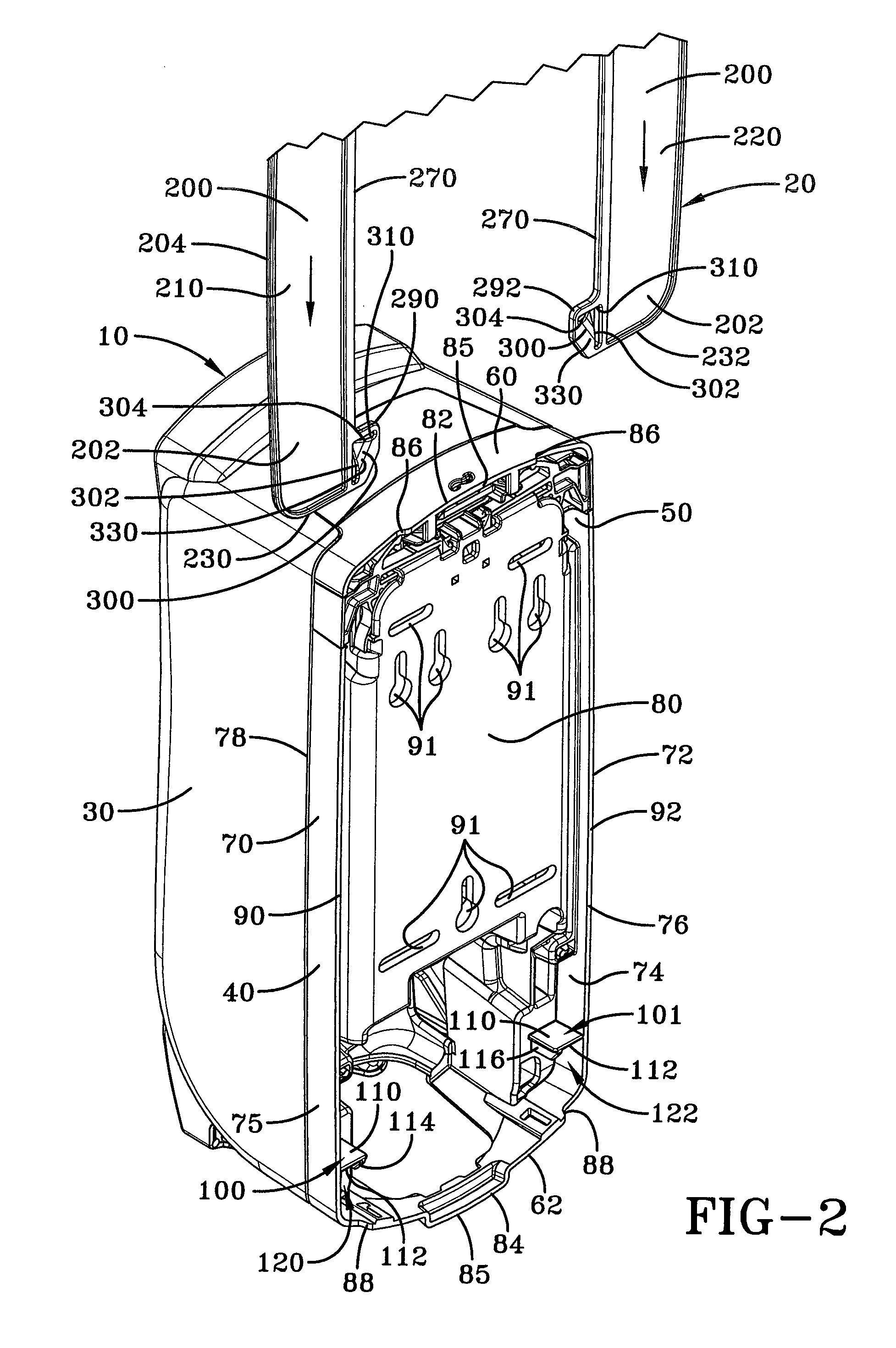
[0029]A utility panel for a dispenser 10 is generally referred to by numeral 20, as shown in the Figs. of the drawings. Specifically, the dispenser 10, as shown in FIGS. 1-3, comprises a cover 30 that is pivotably mounted to a backplate 40. The backplate 40 comprises a substantially rectangular wall 50 that is configured with opposed upper and lower sections 60 and 62 that are joined by opposed lateral sections 70 and 72. The sections 60, 62 and 70, 72 of the wall 50 include inner and outer surfaces 74 and 75 that are bounded by an inner edge 76 and an opposed outer edge 78. Disposed between the respective lateral sections 70, 72 of the wall 50 is a mounting section 80, which is configured to extend beyond the inner edge 76 of the wall 50 of the backplate 40. The upper and lower sections 60, 62 of the wall 50 include respective offset sections 82 and 84 that extend away from the inner edge 76 to form an offset edge 85 that is terminated by respective ends 86 and 88. As such, the inn...


PUM


Abstract

A utility panel for a dispenser that is mounted to a support structure by a backplate includes opposed lateral legs that extend from a main section to form a receiving channel therebetween. The main section is configured to display any desired physical indicia, such as advertising messages, for viewing by the user of the dispenser, while the lateral sections include retention tabs that are received within guide channels formed between the backplate and the support structure. As the utility panel is attached to the dispenser, the blackplate is received within the receiving channel of the utility panel until the retention tabs are snap-fit into corresponding lock channels provided by the backplate of the dispenser. As such, the utility panel is easily retrofit to a previously-installed dispenser without the use of tools.

Description

TECHNICAL FIELD[0001]Generally, the present invention relates to dispensers for dispensing material, such as soap. In particular, the present invention relates to a utility panel configured to be retrofit to an installed dispenser. More particularly, the present invention relates to a utility panel configured to be readily retrofit to a compatible backplate, such as that provided by a previously-installed dispenser.BACKGROUND ART[0002]Dispensers have been installed in many locations where there is a need for the convenient dispensing of material, such as soap, sanitizer, or moisturizer therefrom. Because these dispensers provide a convenient source of material, they offer opportunities in which informational content can be communicated to the users of the dispenser.[0003]Unfortunately, existing dispensers fail to provide a system in which advertisements or other informational content can be provided, and as such, opportunities to communicate such messages with the users of the dispe...

Claims


Application Information

Patent Timeline
Patent Type & Authority Patents(United States)
IPC IPC(8): B67D7/06G09F3/10G09F19/00B65H1/00B67D1/07
CPCG09F7/18G09F23/00G09F23/06G09F3/204G09F2007/1869G09F2023/0025A47K5/12G09F23/0081
Inventor CIAVARELLA, NICKDECARLO, DEANHAYES, DAVID D.
Owner GOJO IND INC
Why Eureka
Try Eureka