Spray nozzle for liquid and device for spraying liquid comprising such a nozzle

a technology of spray nozzle and liquid, which is applied in the direction of combustion process, burner, combustion type, etc., can solve the problems of reducing the quality of spraying, asymmetric wear reducing the service life of the spray nozzle, so as to improve the spraying quality and the effect of long service li

Inactive Publication Date: 2013-11-26
EXCEL IND INC
View PDF9 Cites 4 Cited by
  • Summary
  • Abstract
  • Description
  • Claims
  • Application Information

AI Technical Summary

Benefits of technology

[0011]The present invention aims in particular to solve these drawbacks by proposing a spray nozzle with a longer service life and enabling a flat jet to be produced with a relatively uniform distribution of liquid, and therefore to improve the spraying quality.

Problems solved by technology

The “tails effect” has the drawback of leading to asymmetric wear of the nozzle 1, by overwearing down the edges of the orifice 7.
The more abrasive the sprayed liquid is, the greater this wear is.
This wear increases the “tails effect” and therefore leads to a reduction in the quality of the spraying.
In addition, it reduces the service life of the nozzle 1, even when the material of the body 2 has a high hardness.
However, the nozzle of GB-A-1 312 052 does not permit to significantly decrease the “tails effect” so as to get a sufficient spraying quality.

Method used


Image

  • Spray nozzle for liquid and device for spraying liquid comprising such a nozzle
  • Spray nozzle for liquid and device for spraying liquid comprising such a nozzle
  • Spray nozzle for liquid and device for spraying liquid comprising such a nozzle

Examples


Embodiment Construction

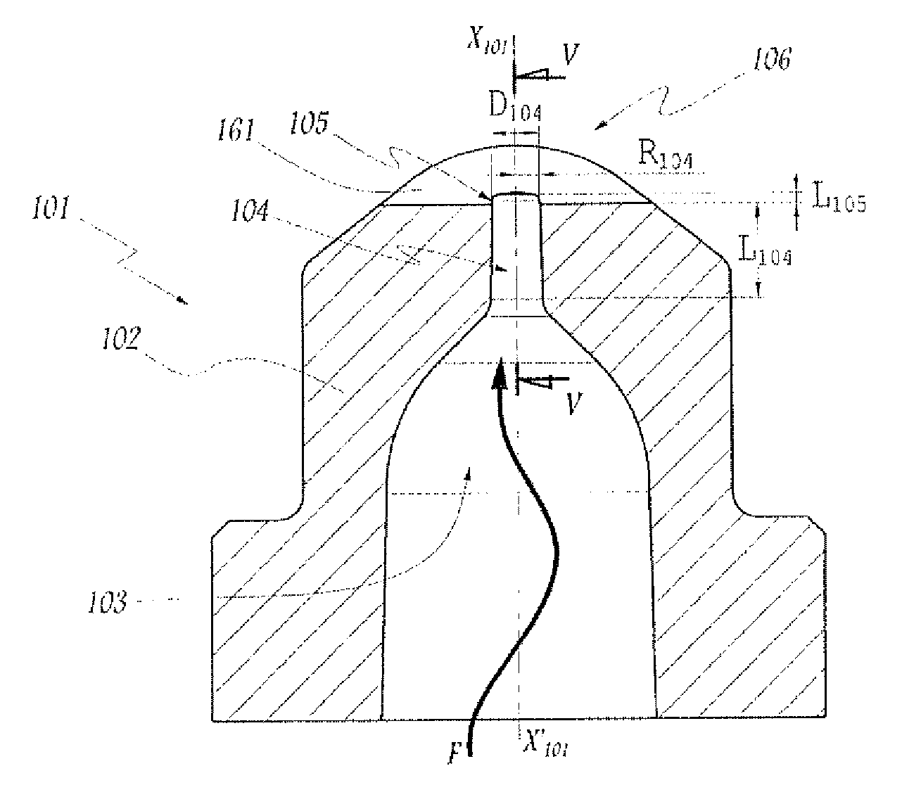
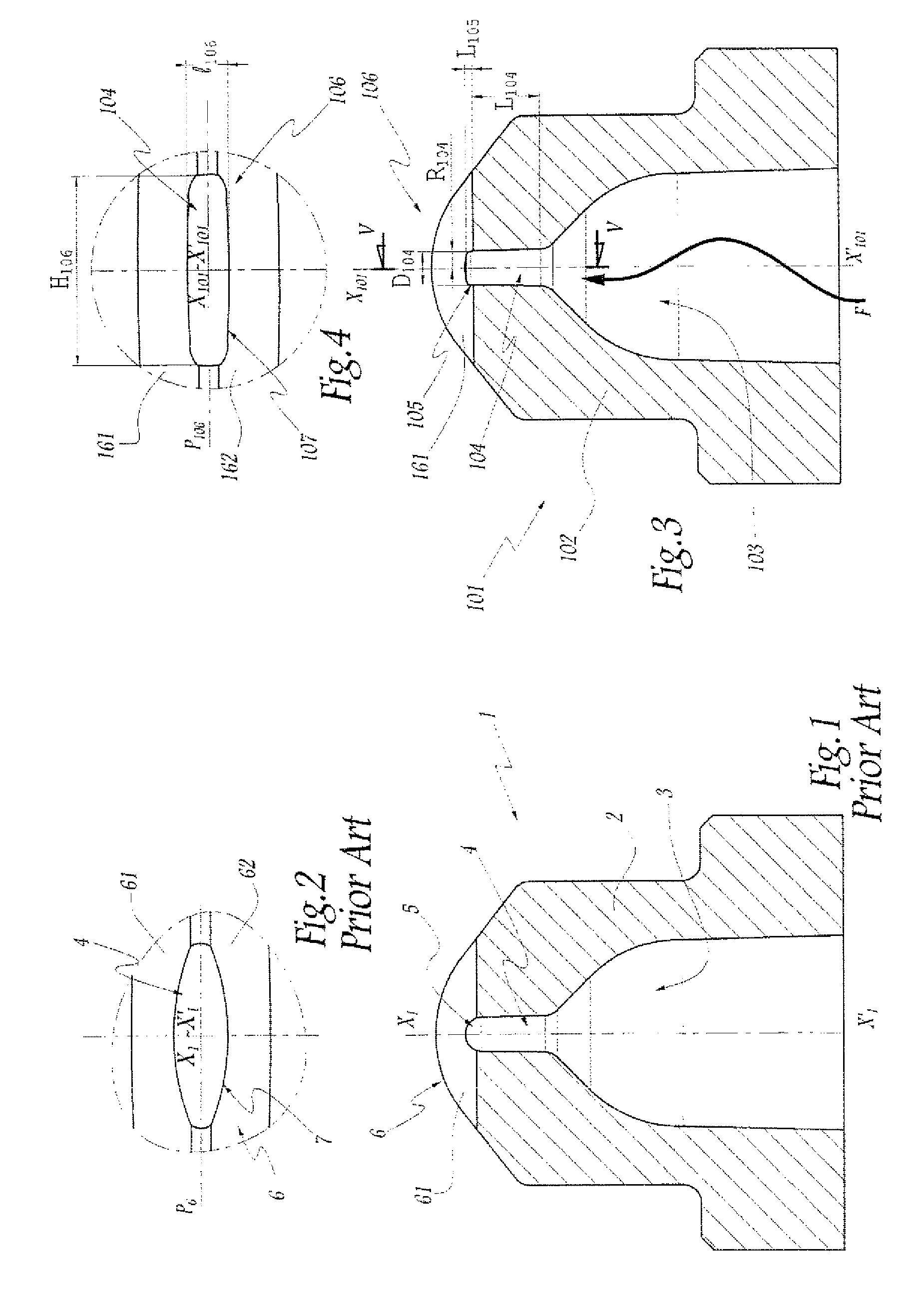
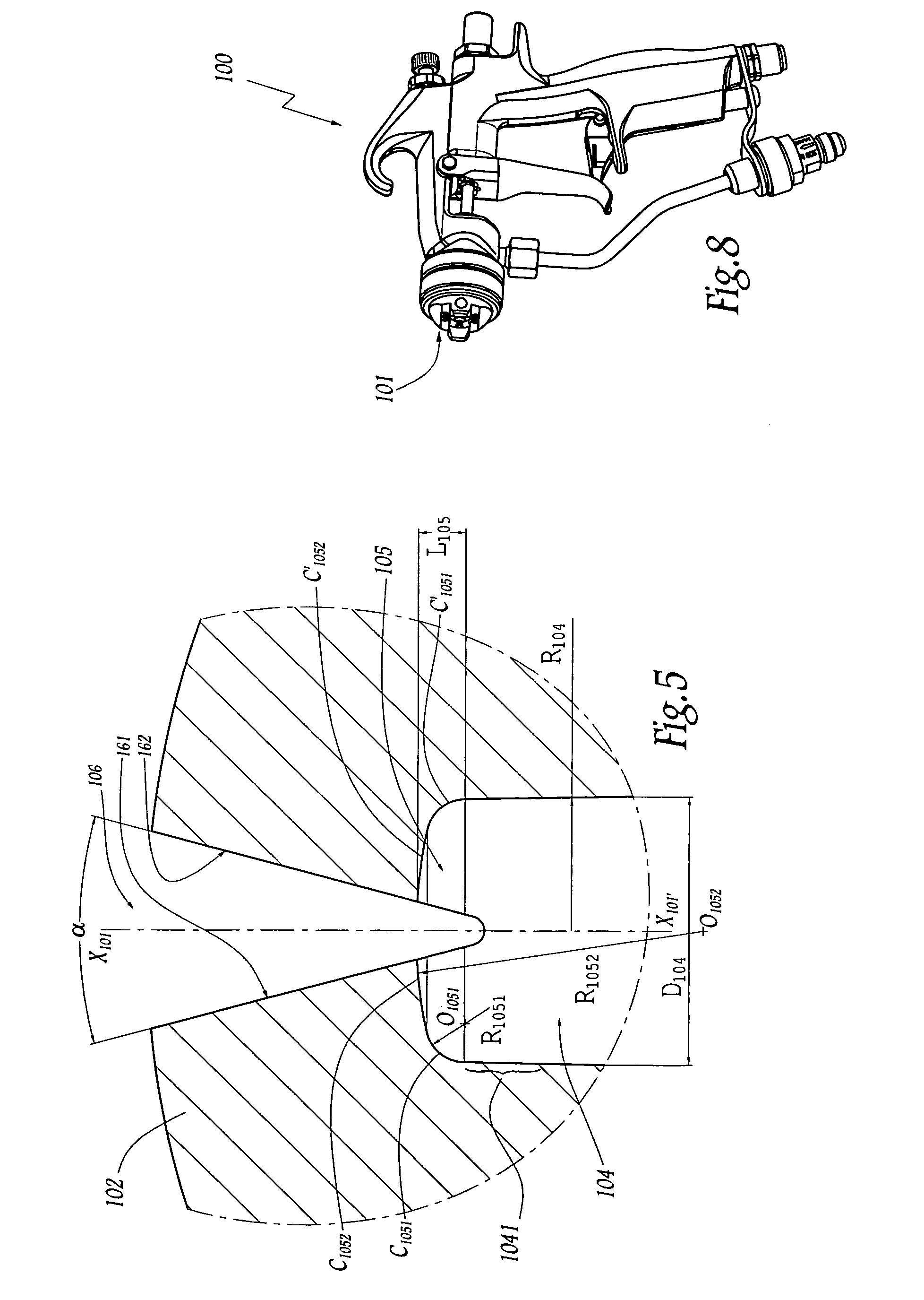
[0037]As FIG. 3 shows, the nozzle 101 comprises a body 102 which defines, on the upstream side, a chamber 103 through which the liquid arrives and, on the downstream side, a channel 104 for conveying the liquid from the chamber 103 through to the outlet of the nozzle 101. The direction of flow of the fluid through the nozzle 101 is represented by an arrow F, which then allows to notice the upstream and downstream sides of the nozzle 101.

[0038]The chamber 103 and the channel 104 extend along a longitudinal axis X101-X′101 of the nozzle 101. In the example of FIG. 3, the channel 104 has the overall form of a cylinder with an axis X101-X′101 and a circular base of diameter D104. Downstream of the channel 104, the nozzle 101 comprises a slot 106 intended to shape the liquid jet into a flat spray. As FIGS. 3 and 4 show, the slot 106 is formed by two surfaces 161 and 162 which are plane, which converge in the direction of the channel 104, and which are positioned on either side of a plane...


PUM


Abstract

A spray nozzle includes a tubular channel extending along a longitudinal axis, a slot formed by two approximately plane surfaces converging in a direction of the channel and located on either side of a plane including the longitudinal axis of the channel, and a dome connecting the channel and the slot wherein a length of the dome represents less than 50% of a largest transverse dimension of the channel and a plane cross section of the dome is symmetric and it is defined by at least two different circular arcs.

Description

BACKGROUND OF THE INVENTION[0001]1. Field of the Invention[0002]The present invention relates to a spray nozzle for liquid, in particular for coating liquid under high pressure. Furthermore, the invention relates to a device for spraying liquid, in particular for coating liquid under high pressure, comprising such a nozzle.[0003]2. Brief Description of the Related Art[0004]A device for spraying liquid or sprayer, either of the manual type or of the automatic type, generally comprises a spray nozzle, sometimes several, which is(are) mounted at the downstream end of the sprayer. The terms “upstream” and “downstream” herein refer to the direction of flow of the liquid in the sprayer. The term “upstream” denotes elements located on the side of the sprayer where the liquid to be sprayed arrives from a supply source. The term “downstream” denotes elements located on the side of the sprayer where the liquid is sprayed in droplets.[0005]Such a sprayer may, for example, be intended for spray...

Claims


Application Information

Patent Timeline
Patent Type & Authority Patents(United States)
IPC IPC(8): B05B1/00
CPCB05B1/042B05B1/048
Inventor BALLU, PATRICK
Owner EXCEL IND INC
Why Eureka
Try Eureka