
Reagent storage in microfluidic systems and related articles and methods

a technology of microfluidic systems and reagents, applied in fluid controllers, laboratory glassware, instruments, etc., can solve the problems of adding a level of cost and sophistication, and achieve the effect of preventing evaporation and/or contamination

Active Publication Date: 2013-11-26
OPKO DIAGNOSTICS
View PDF127 Cites 66 Cited by
  • Summary
  • Abstract
  • Description
  • Claims
  • Application Information

AI Technical Summary

Benefits of technology

The patent describes a fluidic device that comprises two microfluidic channels formed in a single article. The device includes an intervening channel that connects the two microfluidic channels. The device is pre-sterilized to prevent evaporation and contamination of the channels. The technical effects of this invention include a more efficient and reliable fluidic device for chemical and biological applications.

Problems solved by technology

While various microfluidic methods and devices, such as microfluidic assays, can provide inexpensive, sensitive and accurate analytical platforms, the handling and storage of fluids—such as sample introduction, introduction of reagents, storage of reagents, separation of fluids, modulation of flow rate, collection of waste, extraction of fluids for off-device analysis, and transfer of fluids from one device to the next—can add a level of cost and sophistication.

Method used


Image

  • Reagent storage in microfluidic systems and related articles and methods
  • Reagent storage in microfluidic systems and related articles and methods
  • Reagent storage in microfluidic systems and related articles and methods

Examples


example 1

Fabrication of Fluidic Devices

[0151]Method for fabricating a fluidic device are described.

[0152]A channel system of a fluidic device was designed with a computer-aided design (CAD) program. The device was formed in poly(dimethylsiloxane) Sylgard 184 (PDMS, Dow Corning, Ellsworth, Germantown, Wis.) by rapid prototyping using masters made in SU8 photoresist (MicroChem, Newton, Mass.). The masters were produced on a silicon wafer and were used to replicate the negative pattern in PDMS. The masters contained two levels of SU8, one level with a thickness (height) of ˜70 μm defining the channels in the immunoassay area, and a second thickness (height) of ˜360 μm defining the reagent storage and waste areas. Another master was designed with channel having a thickness (height) of 33 μm. The masters were silanized with (tridecafluoro-1,1,2,2-tetrahydrooctyl)trichlorosilane (ABC-R, Germany). PDMS was mixed according to the manufacturer's instructions and poured onto the masters. After polymer...

example 2

Fabrication and Testing of Fluidic Devices for Reagent Storage

[0154]A method for fabricating and testing a fluidic device that can be used to store reagents is described.

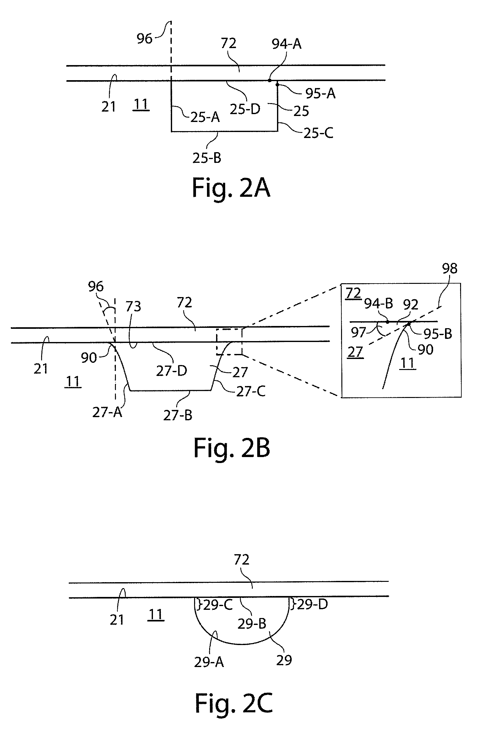
[0155]In this example, a microfluidic channel was used as a storage vessel. This microchannel was created by fabricating a channel in a plastic substrate using injection molding and sealing the channel with an adhesive tape to produce a fluid-tight seal. This fabrication method resulted in a microchannel with a trapezoidal cross section. Under a microscope, the corners of the trapezoidal microchannels were not perfect corners, but instead were curved, with a radius of curvature significantly smaller than the half-depth (or half-width, whichever is smaller) of the microchannel.

[0156]FIG. 8A shows a schematic diagram of a portion of a microchannel 600 that was fabricated. Multiple liquid plugs 610 (only one of which is shown) were stored in portions of the channel having a substantially trapezoidal cross section, the ...


PUM


Abstract

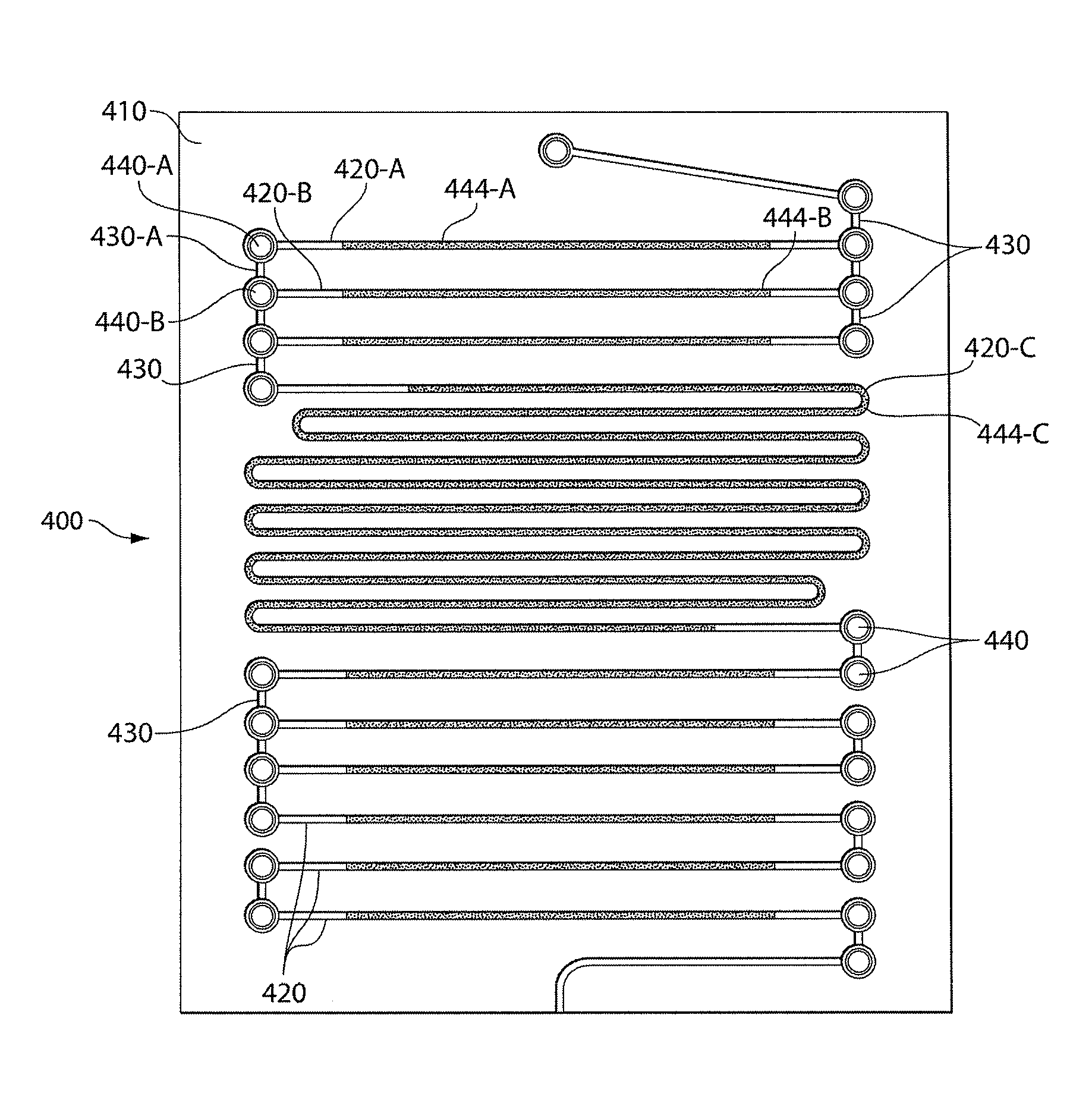
Fluidic devices and methods including those that provide storage and / or facilitate fluid handling of reagents are provided. Fluidic devices described herein may include channel segments positioned on two sides of an article, optionally connected by an intervening channel passing through the article. The channel segments may be used to store reagents in the device prior to first use by an end user. The stored reagents may include fluid plugs positioned in linear order so that during use, as fluids flow to a reaction site, they are delivered in a predetermined sequence. The specific geometries of the channel segments and the positions of the channel segments within the fluidic devices described herein may allow fluid reagents to be stored for extended periods of time without mixing, even during routine handling of the devices such as during shipping of the devices, and when the devices are subjected to physical shock or vibration.

Description

RELATED APPLICATIONS[0001]This application claims priority under 35 U.S.C. §119(e) to U.S. Provisional Patent Application No. 61 / 138,726, filed Dec. 18, 2008, and entitled “Improved reagent storage in microfluidic systems and related articles and methods”, which is incorporated herein by reference in its entirety for all purposes.FIELD OF INVENTION[0002]The present invention relates generally to fluidic devices, and more specifically, to microfluidic systems and methods that provide fluid handling and storage of reagents.BACKGROUND[0003]The manipulation and storage of fluids plays an important role in fields such as chemistry, microbiology and biochemistry. These fluids may include liquids or gases and may provide reagents, solvents, reactants, or rinses to chemical or biological processes. While various microfluidic methods and devices, such as microfluidic assays, can provide inexpensive, sensitive and accurate analytical platforms, the handling and storage of fluids—such as sampl...

Claims


Application Information

Patent Timeline
Patent Type & Authority Patents(United States)
IPC IPC(8): B01L3/00
CPCB01L3/5027B01L3/527B01L3/561B01L2200/0673B01L2200/12B01L2200/142B01L2200/16B01L2300/069B01L2300/0809B01L2300/0874B01L2300/161B01L2300/0883B01L2400/0487
Inventor TAYLOR, JASONLINDER, VINCENT
Owner OPKO DIAGNOSTICS
Learn More