Chamber of a bioreactor platform

Inactive Publication Date: 2011-09-29
SMART BIOSYST
View PDF6 Cites 18 Cited by
  • Summary
  • Abstract
  • Description
  • Claims
  • Application Information

AI Technical Summary

Benefits of technology

[0019]The chamber contained in the mesoscale bioreactor platform of the invention is particularly suited where it is of interest to be able physically to access the chamber in a convenient manner. The upwards open chamber is provided with a closure of a water-immiscible liquid layered on top of an aqueous liquid in the chamber. The water-immiscible liquid will form a generally homogeneous phase in contact with a sidewall of the chamber defining the perimeter of the open surface of the chamber, thereby substantially preventing evaporation of liquid from the chamber and preventing that the aqueous liquid is contaminated with particles, e.g. microbial germs or pathogens, from the ambient surroundings of the bioreactor platform. The closure will also control the evaporation of solvents and other volatile compounds such as CO2 and O2. Some of the components in the aqueous liquid or media will effectively be hampered in escaping the chamber, such as water vapour, while other components may be exchanged over the closure, such as CO2 and O2. By controlling the transport of CO2 over the closure of water-immiscible liquid the pH may be maintained at a relevant level. Thus, the water-immiscible liquid can be said to provide a semi-pervasive closure for the chamber.
[0023]Biological or biochemical reactions normally take place in aqueous environments, and therefore in one embodiment the chamber for a biological cell comprises an aqueous liquid forming a lower phase in the chamber, so that the water-immiscible liquid forms an upper phase. The water-immiscible phase serves as a closure for the chamber to prevent evaporation and contamination of the aqueous liquid. In order to supply and remove aqueous liquid to or from the chamber, respectively, the lower aqueous phase preferably covers the first port and the second port of the chamber. This positioning of the ports and the aqueous liquid relative to each other will ensure that the water-immiscible phase can be retained on the aqueous liquid as a closure.
[0041]In another aspect the invention relates to using a water-immiscible liquid as a closure for a chamber in a mesoscale bioreactor platform. Herein a mesoscale bioreactor platform comprising an upwards open chamber for a liquid and a first channel communicating with the chamber via a first port is provided prior to applying an aqueous liquid to the chamber of the mesoscale bioreactor platform so that the aqueous liquid covers the first port, applying a water-immiscible liquid of a density lower than that of water on the aqueous liquid in the chamber to form a lower aqueous phase and an upper phase comprising the water-immiscible liquid, inducing a flow of the aqueous liquid from the chamber into said first channel to create an effluent stream, and controlling the pressure of a gas above the chamber relative to the pressure of the gas originating from the aqueous liquid in the chamber in order to control diffusion of the gas into or out of the aqueous liquid.

Problems solved by technology

Such methodology is labour-intensive, as changes of growth media require a large degree of manual handling.
Manual handling always introduces a risk of contamination, and moreover the static conditions do not provide much resemblance with in vivo conditions, as it is difficult to meet the changing needs of an embryo.
The conditions existing in vivo at one stage of development may even be harmful to an embryo at a later stage of development.
Some of the disadvantages of the static-based Petri-dish culturing system may be circumvented by culturing the embryo in a culturing system capable of perfusing the embryo with a growth medium appropriate for its developmental stage.
‘True’ microfluidic devices (e.g. with fluidic channels in the order of 100 μm diameter or less) do however suffer from a number of drawbacks, some of which are particularly pronounced for cell culturing devices designed for perfusion-type operation.
As seen from the Hagen-Poiseuille equation (see below) the pressure drop in an e.g. 100 μm-channel with a flow becomes very large, putting high demands to a pump intended for operating at this scale, since such a pump must be able to precisely dispense very small volumes against a considerable back pressure.
Such electroosmotic flow is however ill suited for systems involving live (mammalian) cells.
Another problem encountered in microfluidics is one related to the ‘connection to the outside world’.
Most equipment employed in biological labs, such as pumps and analytical equipment, is so much larger than microfluidic equipment that integration between the two scales becomes problematic.
Connection points for a tube as small as 250 μm-diameter (as is readily available) to a chip are difficult to handle for the lab worker, and moreover may quickly introduce dead volumes several times the size of the volume of the microfluidic system.
This problem is especially important for perfusion-type cell culture devices where the operational complexity and the long residence times of fluids in tubes connected to a microfluidic system increases the risk of upstream contamination.
Considering the “mass-balance-buffering” effect of the dual-channel design it is unclear how the design may be modified to use such external liquid supplies, and the devices seem ill suited for conducting long-term perfusion type growth experiments, as there is a need to use an outside supply of fluid.
In particular, this design is of little use when two or more reservoir chambers supply the same culturing chamber in a design where all the chambers are thus not serially connected.
It thus appears that the system described in WO2006 / 089354 is ill-suited for perfusive operation, in particular for long-term perfusive operation.
A lack of such dedicated functions make it difficult to predict and control the conditions existing in the culture chamber, and also analysis of effluent fluid from the culture chamber is problematic since effluent fluid in the device of WO2006 / 089354 will inevitably be mixed with fresh medium.
Therefore the system appears ill-suited for perfusing the culture chamber, and in particular a steady state of the liquid level in the chamber could not be achieved.
Despite the efforts discussed above a system has yet to be described to solve the problems of designing a simple fluidic device intended for perfusion type operation on a scale and time appropriate for mammalian cells, such as embryos, where the growth chamber may readily be accessed during operation.

Method used


Image

  • Chamber of a bioreactor platform
  • Chamber of a bioreactor platform
  • Chamber of a bioreactor platform

Examples


example 1

Construction of a Mesoscale Bioreactor Platform

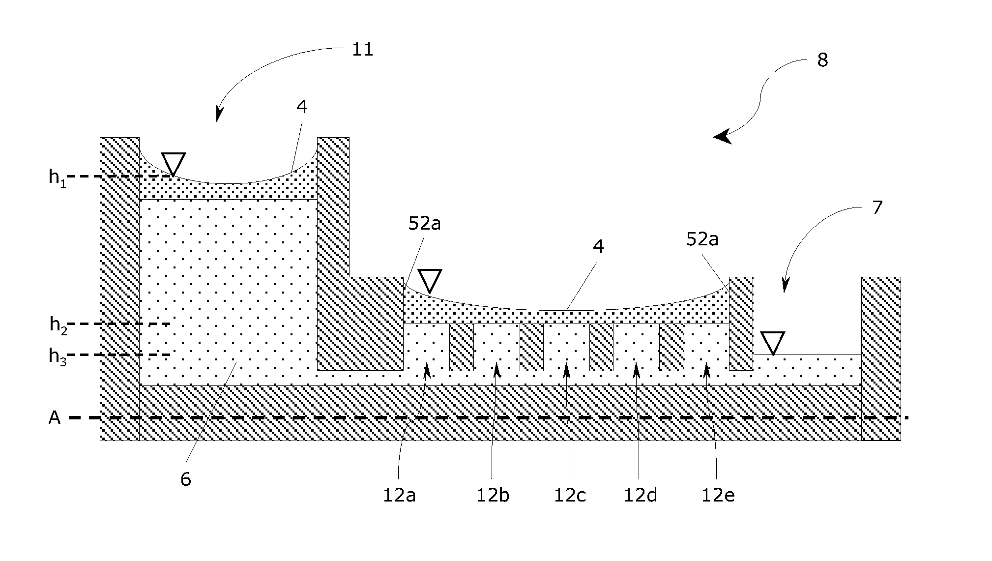
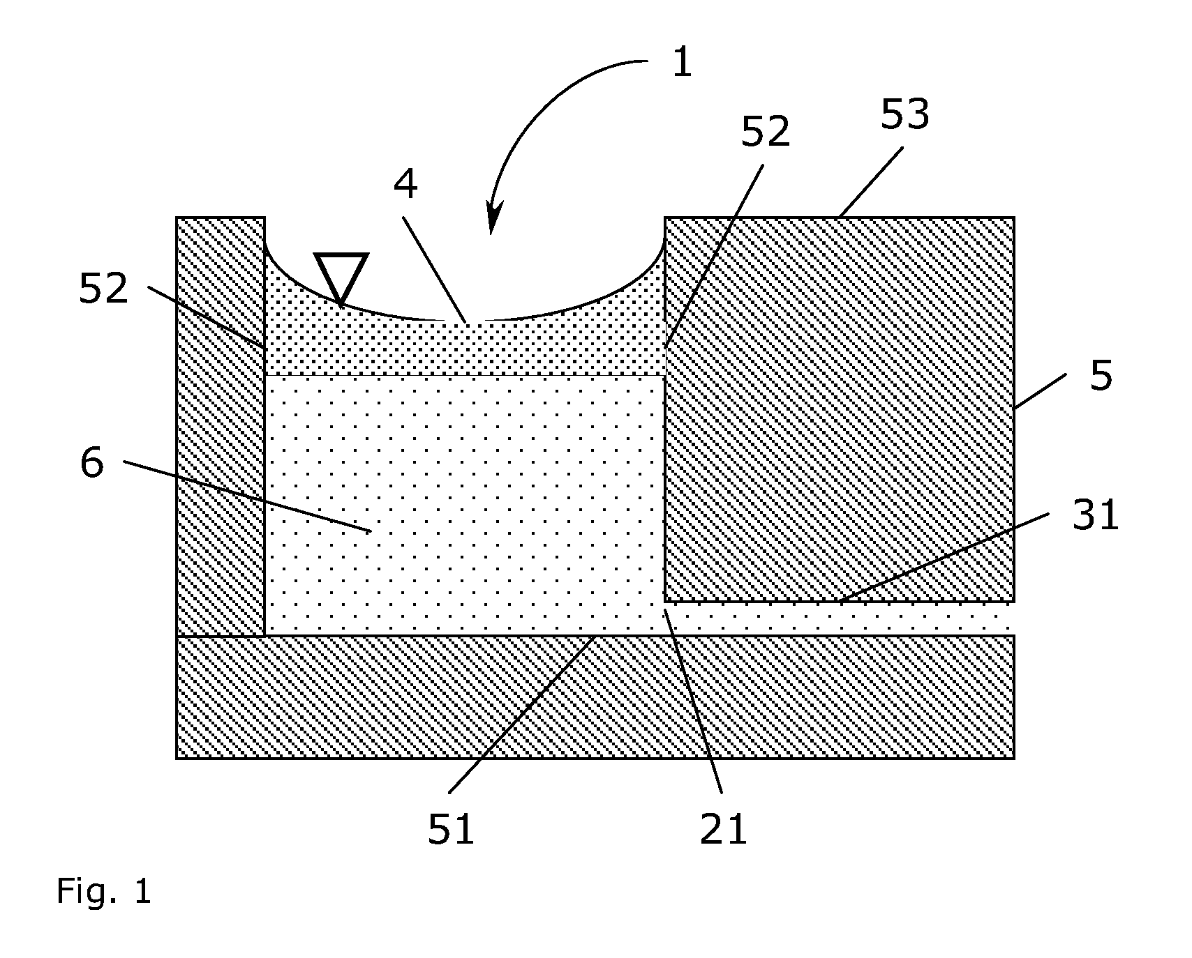
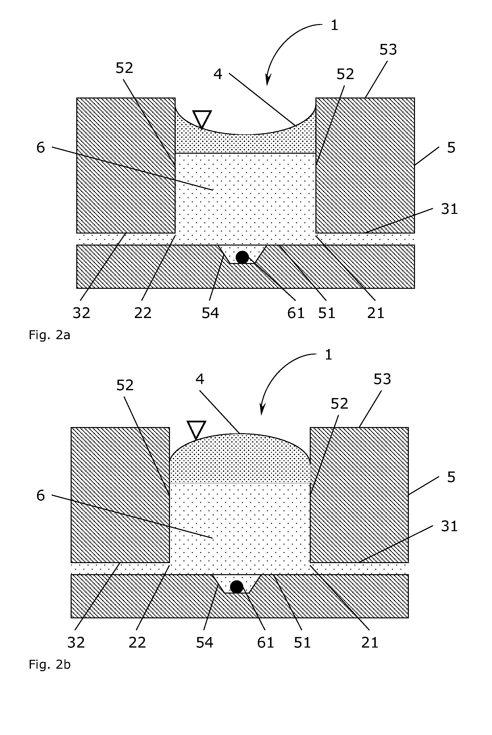
[0110]A prototype mesoscale bioreactor platform consisting of four layers of substrate materials was designed using the 2D drawing software AutoCAD LT (Autodesk, San Rafael, Calif., USA). The bioreactor platform design contained two cylindrical reservoirs of 16 mm diameter and 5 mm depth (1 mL volume), which were connected to a junction by two channels. Each reservoir had a channel allowing to connect the reservoir to the ambient surroundings. A channel from the junction led to three serially connected culture chambers of 4 mm diameter and 1.5 mm depth (similar to a volume of 20 μL). Each culture chamber had a depression of approximately 500 μm diameter and 200 μm in depth in the bottom surface. A waste channel led from the third culture chamber to the ambient surroundings.

[0111]The bottom layer of the design of the bioreactor platform was a rectangular plate (5 cm×8 cm size) with a through-hole of 500 μm diameter and the three depressi...

example 2

Construction of a Mesoscale Bioreactor Platform

[0114]A mesoscale bioreactor platform was designed and constructed as described in Example 1 except the three serially connected culture chambers (in the second substrate layer) were replaced with a single culture chamber of 20 mm diameter (volume 0.5 mL). The bottom of this single culture chamber contained six depression (approximately 500 μm diameter and 200 μm depth) placed on the perimeter of a circle of 10 mm diameter located in the centre of the chamber.

example 3

Construction of a Control Unit

[0115]A suitable box of a polymeric material was selected to construct a proto-type control unit for housing a mesoscale bioreactor platform. The size of the box was approximately 16×24×12 cm3. The box was fitted with a compartment consisting of a smaller box for containing an aluminium block (approximately 10×7×2 cm3), to function as a heat regulating element, and either of the mesoscale bioreactor platforms described in Example 1 or Example 2. The aluminium block was machined to exactly house the bioreactor platform, and a hole (1 mm diameter) was drilled in it in a location corresponding to the location of the exit of the mesoscale bioreactor platform. The opening of the hole was expanded to house a rubber O-ring (1 mm ID), and the exit hole fitted with a piece of 0.5 mm ID Teflon tube which was connected to micro-scale pH-electrode further being connected to a 2 mL syringe pump. In an alternative design the exit hole was connected to a 360 μm diamet...


PUM


Abstract

Disclosed herein is mesoscale bioreactor platform comprising an upwards open chamber for a biological cell, which chamber via a first port is in communication with a first channel for conducting an influent stream of a liquid into the chamber and via a second port is in communication with a second channel for conducting an effluent stream of a liquid away from the chamber, which chamber is provided with a closure comprising a water-immiscible liquid, and wherein said first channel is in fluid communication with a reservoir for a liquid and said second channel is in fluid communication with a waste container. Furthermore, a method for modifying the interaction of a content of a chamber with the surroundings is described as well as method of culturing a biological cell.

Description

FIELD OF THE INVENTION[0001]This invention relates to a mesoscale bioreactor comprising a chamber for a biological cell, a channel for an influent stream and a channel for an effluent stream and a layer of a water-immiscible fluid as a closure on the chamber, wherein the channels are in fluid communication with a reservoir for a liquid and a waste container, respectively. The invention also relates to a method for modifying the interaction of the content of the chamber with the surroundings, and a method for culturing a biological cell. The mesoscale bioreactor is suited for culturing biological cells; it is especially suited for culturing mammalian cells, such as embryos or stem cells. More particularly it is suited for use in in vitro fertilisation procedures.PRIOR ART[0002]The procedures currently employed in in vitro fertilisation (IVF) for embryo culture rely on culturing the embryos in Petri-dishes under static conditions. Such methodology is labour-intensive, as changes of gr...

Claims


Application Information

Patent Timeline
IPC IPC(8): C12N5/07C12M1/00C12N5/071C12N1/20C12N1/16C12N1/14C12N5/04
CPCB01L3/5027C12M41/40C12M29/10C12M23/12
Inventor LARSEN, JACOB MOLLENBACHKRUHNE, ULRICH
Owner SMART BIOSYST
Why Eureka
Try Eureka