Tyre having a member with an offset antenna

a technology of offset antenna and tyre, which is applied in the direction of tyre parts, transportation and packaging, and other domestic articles, can solve the problems of antennas that are not suitable for withstanding additional stresses, sidewall stress field disruption, and connection breakage, so as to achieve the effect of reducing the drawback

Active Publication Date: 2013-11-26
MICHELIN & CO CIE GEN DES ESTAB MICHELIN
View PDF17 Cites 9 Cited by
  • Summary
  • Abstract
  • Description
  • Claims
  • Application Information

AI Technical Summary

Benefits of technology

[0010]By virtue of an embodiment of the invention, the antenna is integrally offset radially on one side of the device at a distance such that the zone of the sidewall in which the antenna is placed is not disrupted by the presence of the electronic chip. Consequently, the antenna is situated in a zone in which the forces are essentially circumferential and uniform. As has been seen above, it is possible to design antennas that withstand circumferential forces. The radial orientation of the means of electrical connection between the wire antenna and the electronic device allows them to better withstand the stresses sustained close to the electronic device because the field of stresses is principally circumferential.
[0011]Therefore, by virtue of the offsetting of the antenna relative to the chip, the stresses applied to the antenna are more uniform and the service life of the member is thereby lengthened.
[0018]The sidewall comprising a bead in a radially internal portion, the device is embedded in the side wall in the vicinity of the bead and the antenna is offset in a direction radially external to the tyre. The electronic device and its connections with the means of electrical connection to the antenna are relatively fragile. It is therefore recommended to position them in a zone of the sidewall where there are not many mechanical stresses. The radially internal zone of the sidewall, close to the bead, sustains few deformations because it is reinforced by the carcass ply and by the circumferential bead wire embedded in the bead. It is therefore advantageous to place the device in this zone. Conversely, because of the proximity of the bead wire and of the carcass ply, it is not recommended to position the antenna in this zone because these various metal elements disrupt the transmitted waves. Therefore, by virtue of an embodiment of the invention and of the radial offset of the antenna relative to the device, it is possible to position the device in the vicinity of the bead and to offset the antenna in a direction radially external to the tyre to the extent of positioning it in a location of the sidewall where electromagnetic conditions are more favourable, for example in a location of the sidewall in which the thickness of rubber is reduced.
[0019]The tyre comprising at least one annular bead wire of revolution about a reference axis and a carcass ply of generally toroidal shape coaxial with the bead wire, comprising a portion folded around the bead wire, the member is in a plane extending radially, travelling away from the reference axis, from a free edge of the folded portion of the carcass ply to a circumferential line of junction between the plane and the carcass ply. This location is particularly advantageous for positioning the electronic device because it sustains very few deformations because of the proximity to the carcass ply and its portion folded around the bead wire.
[0022]The sidewall includes a shoulder in the radially external portion, and the device is embedded in the sidewall in the vicinity of the shoulder and the antenna is offset in a direction that is radially internal to the tyre. The shoulder is located at the junction between the sidewall and the tread of the tyre. This is a zone of great thickness in which the deformations are slight. Consequently, positioning the chip close to the shoulder ensures that it will sustain few stresses, which increases its service life. Moreover, axially offsetting the antenna towards the radially internal portion of the sidewall makes it possible to place the antenna in a location of the sidewall that is relatively thin, that is to say in a location in which the rubber and carcass ply produce only slight electromagnetic interference.

Problems solved by technology

However, the presence of the non-stretchable chip embedded inside the sidewall is the cause of disruption of the stress fields that are in the sidewall.
However, these antennas are not suitable for withstanding the additional stresses created by the presence of the electronic chip and its induced disrupting effects.
Consequently, a fatigue of the antenna is frequently seen at its junction with the chip, this fatigue being able to cause a breakage of the connection after a high mileage.

Method used


Image

  • Tyre having a member with an offset antenna
  • Tyre having a member with an offset antenna
  • Tyre having a member with an offset antenna

Examples


Embodiment Construction

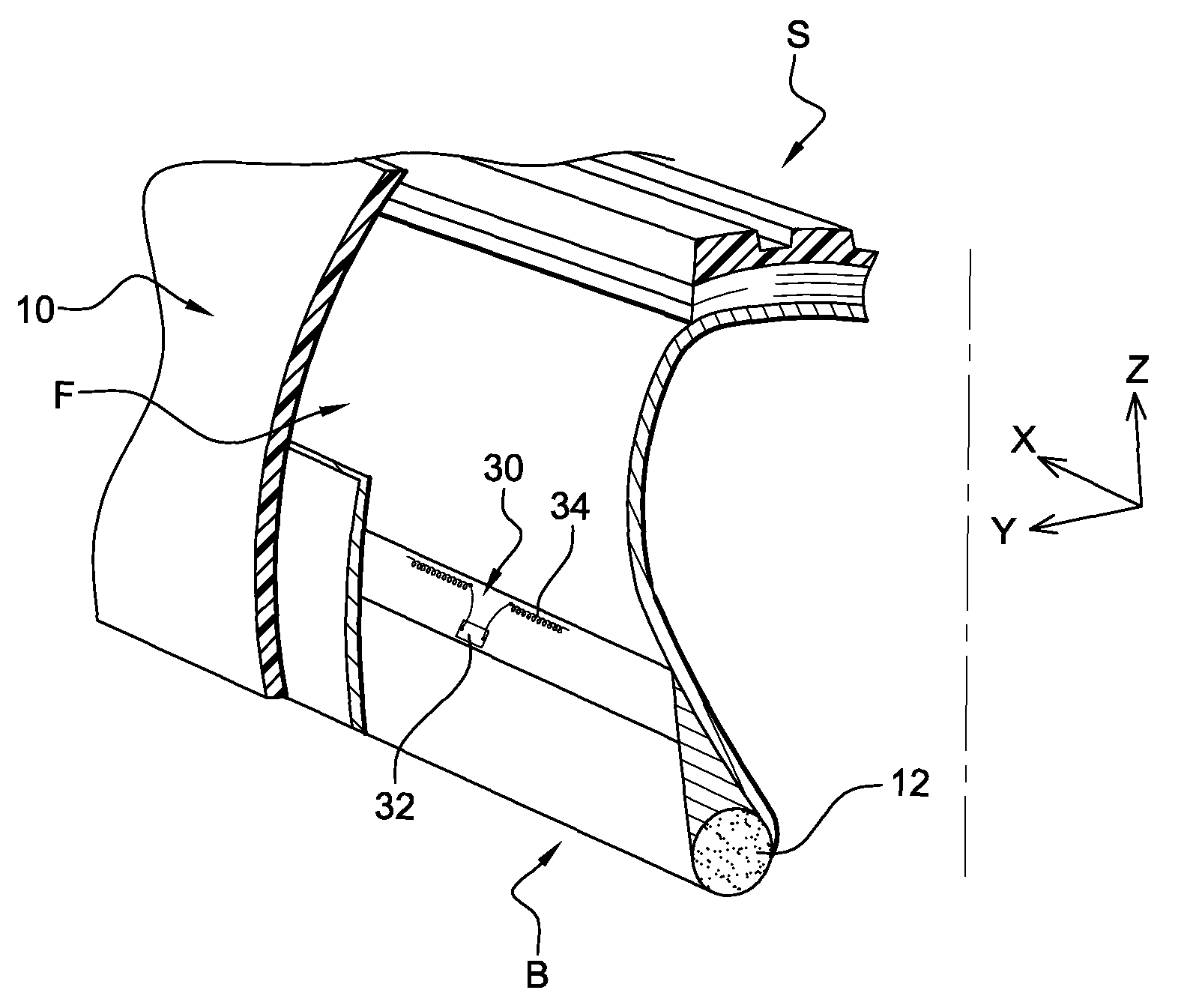
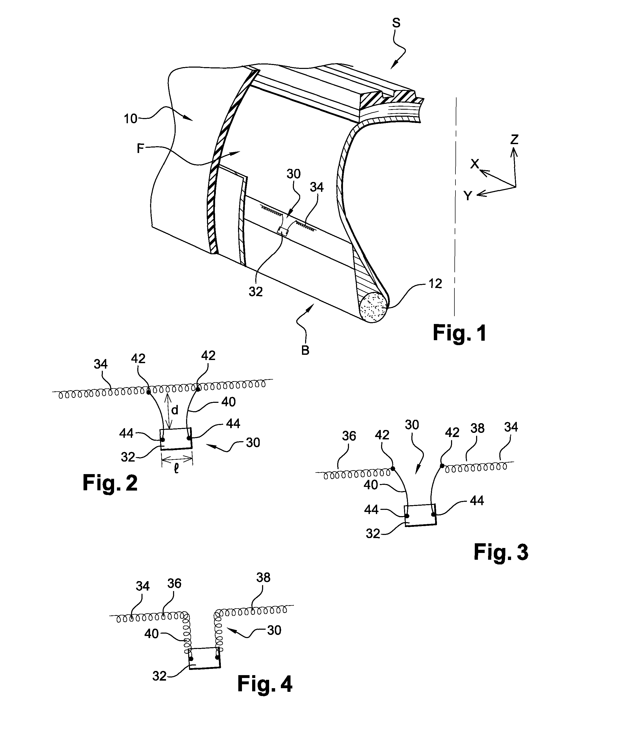
[0031]In the figures are shown axes X, Y, and Z that are orthogonal with one another in the usual orientations, radial (Z), axial (Y), and circumferential (X) of a tyre.

[0032]FIGS. 1, 7, and 8 show a tyre according to an embodiment of the invention, designated by the general reference 10. In this instance, the tyre 10 is intended to be mounted on a wheel of a motor vehicle of the lorry type.

[0033]Conventionally, the tyre 10 comprises a crown S extended by two sidewalls F (only one of which is shown in the figures). The radially internal portion of the sidewall F comprises a bead B and the radially external portion of the sidewall F comprises a shoulder E situated on the border between the sidewall F and the crown S.

[0034]A bead wire 12 is embedded in the bead B.

[0035]The bead wire 12 is of revolution about a reference axis. This reference axis, substantially parallel to the direction Y, is substantially indistinguishable from an axis of revolution of the tyre.

[0036]The crown S compr...


PUM


Abstract

A motor-vehicle tire includes a sidewall and a member with an electronic device, a generally and substantially linear-shaped rectilinear wire antenna, and means of electrical connection between the wire antenna and the electronic device. The member is embedded in the sidewall in an arrangement such that the antenna is oriented circumferentially with respect to the tire and the connection means is oriented in a radial direction of the tire. The wire antenna is integrally offset radially on one side of the electronic device.

Description

FIELD OF THE INVENTION[0001]The invention relates to the field of motor-vehicle tyres, notably tyres incorporating an electronic member for controlling or measuring certain parameters.BACKGROUND OF THE INVENTION[0002]In the rest of the description, the general shape of the tyre is similar to a torus. Therefore, directions that are axial, radial, and circumferential to the tyre are defined relative to this torus.[0003]Document WO 2004 / 011285 discloses a member comprising an electronic device such as an RFID (Radio Frequency Identification) chip to which a linear antenna is connected comprising two branches connected on either side of the chip.[0004]The electric member disclosed in this document is supported by a sidewall of the tyre in a configuration such that the wire antenna is oriented in a circumferential direction of the tyre.[0005]When the tyre is running on the ground, and notably when its tread is in the contact area, the sidewalls of the tyre deform, which generates circumf...

Claims


Application Information

Patent Timeline
Patent Type & Authority Patents(United States)
IPC IPC(8): H01Q1/32
CPCB60C23/0452B60C23/0493H01Q1/2241B29D2030/0077
Inventor MYATT, DAVID
Owner MICHELIN & CO CIE GEN DES ESTAB MICHELIN
Why Eureka
Try Eureka