Condenser microphone

a condenser microphone and microphone technology, applied in the direction of electrical transducers, transducer types, piezoelectric/electrostrictive transducers, etc., can solve the problem that the method cannot be applied to a microphone, and achieve the effect of high reliability of the microphone cord

Active Publication Date: 2006-03-02
AUDIO-TECHNICA
View PDF11 Cites 18 Cited by
  • Summary
  • Abstract
  • Description
  • Claims
  • Application Information

AI Technical Summary

Benefits of technology

[0022] According to these configurations, since the fixing member is surely fixed in the support enclosure, the microphone cord can withstand any stress in the pulling-out, pressing, and rotating directions applied to the microphone cord, so that a fixation state with high reliability of microphone cord can be obtained.

Problems solved by technology

However, although being effective for the gun microphone or the like, this method cannot be applied to a microphone in which, as in the conventional example, the microphone capsule and the output module section are separated from each other and are connected to each other via the microphone cord.

Method used


Image

  • Condenser microphone
  • Condenser microphone
  • Condenser microphone

Examples


Embodiment Construction

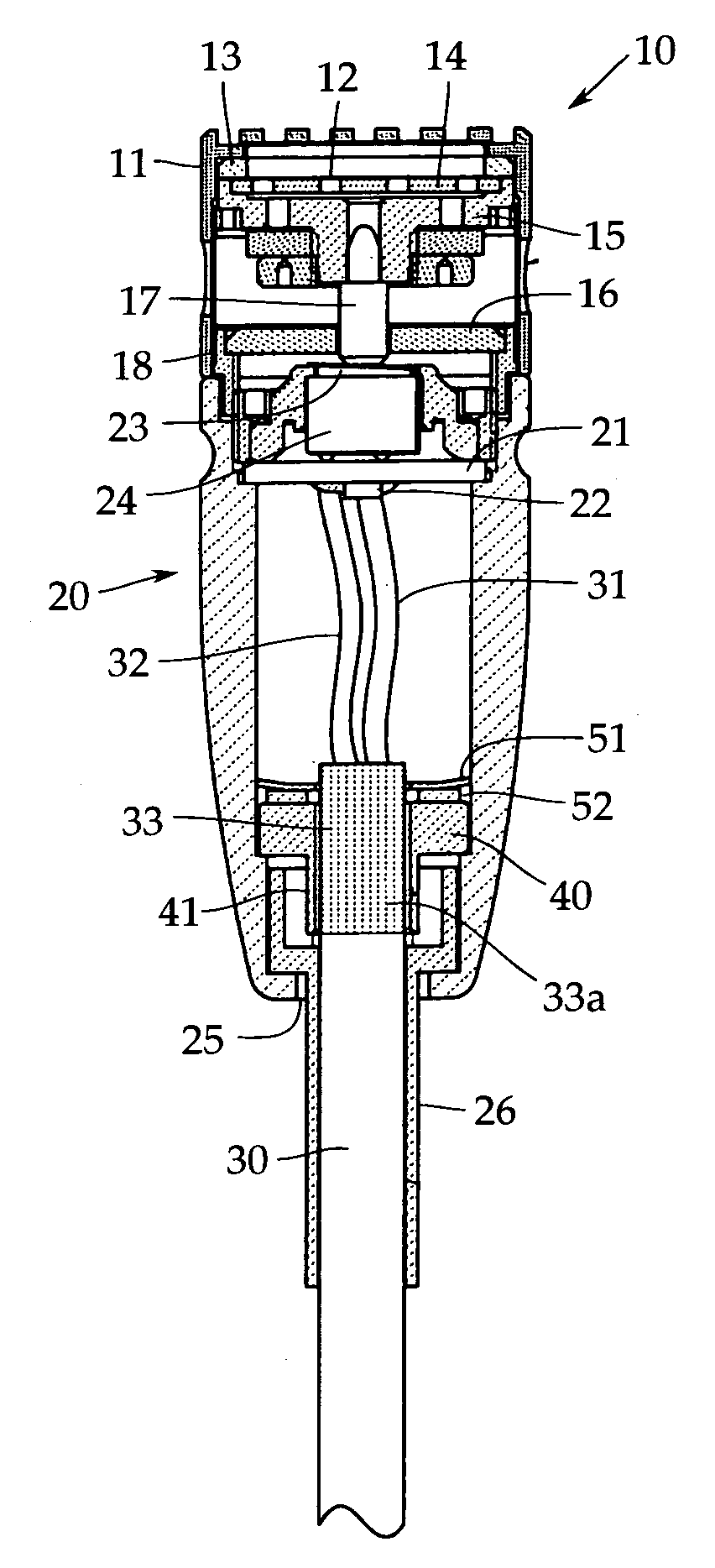
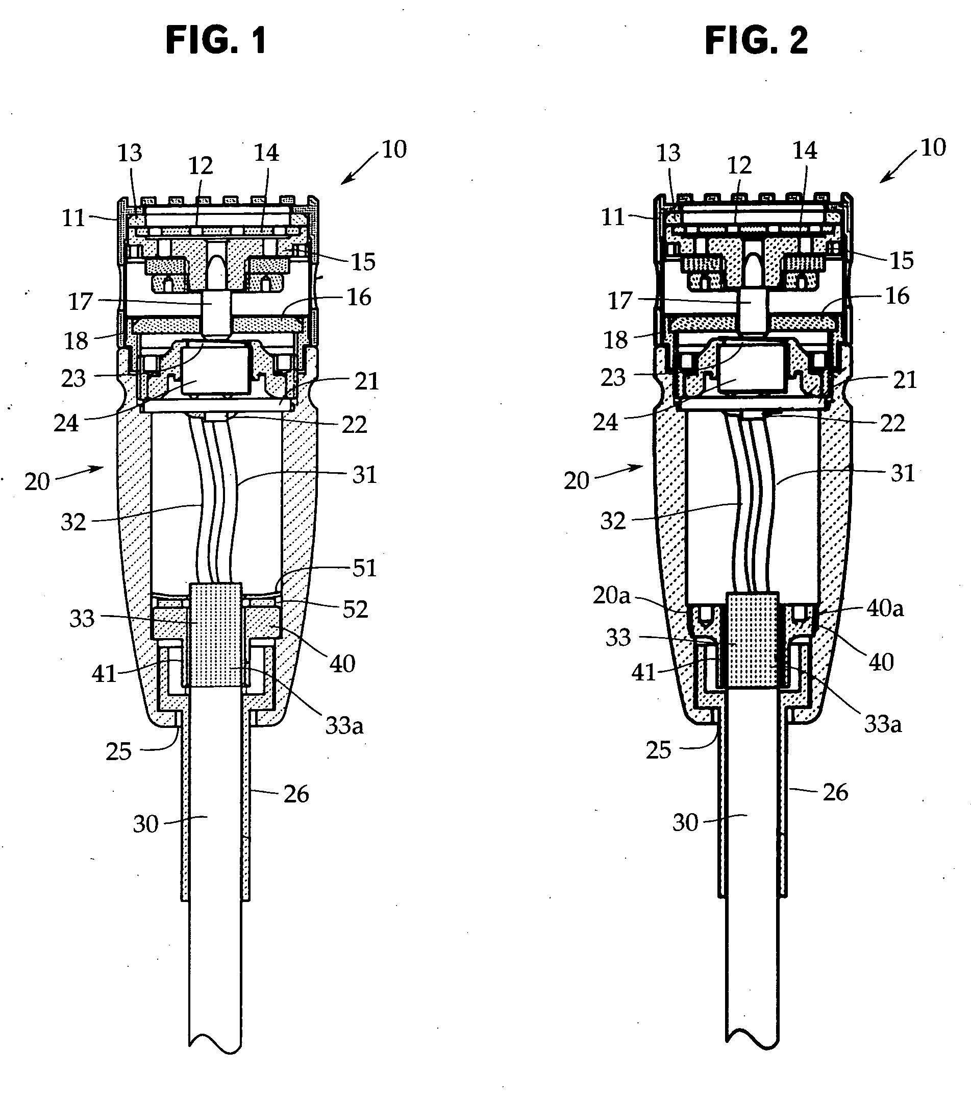
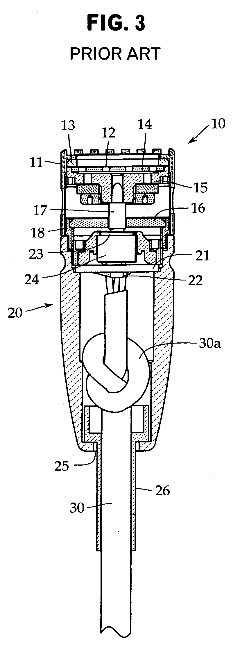
[0026] An embodiment of the present invention will now be described with reference to FIGS. 1 and 2. The present invention is not limited to the embodiment described below. FIG. 1 is a sectional view showing one example of a condenser microphone unit in accordance with the present invention, and FIG. 2 is a sectional view showing another example thereof. In FIGS. 1 and 2, the same reference numerals are applied to elements that are the same or regarded as the same as the elements in the conventional example explained before with reference to FIG. 3, and explanation is sometimes replaced with the reference numeral.

[0027] A condenser microphone in accordance with the present invention includes a microphone unit and an output module section that are connected to each other via a microphone cord. FIGS. 1 and 2 show only the microphone unit side of these elements as in the case of FIG. 3. The output module section is provided with at least an audio output circuit, and the power source m...


PUM


Abstract

In a condenser microphone unit connected to an output module section via a dedicated microphone cord, the generation of noise caused by strong electromagnetic waves sent from a cellular phone etc. is effectively prevented by a simple configuration. In the condenser microphone unit in which a microphone capsule 10 is supported, for example, exchangeably on a support enclosure 20 and a microphone cord 30 consisting of a two-core shield covering line for connecting the condenser microphone unit to the output module section is pulled into the support enclosure 20, a shield covering line exposure portion 33a, in which a shield covering line 33 is stripped off, is provided in a portion in which the microphone cord 30 is pulled into the support enclosure 20, and a fixing member 40 formed into a doughnut shape is fixed to the shield covering line exposure portion 33a by staking, by which the shield covering line 33 is connected to the support enclosure 20 via the fixing member 40.

Description

TECHNICAL FIELD [0001] The present invention relates to a condenser microphone in which a condenser microphone unit and an output module section having an audio output circuit are connected to each other via a dedicated microphone cord. More particularly, the present invention relates to a technique for preventing the generation of noise caused by electromagnetic waves applied to the microphone cord. BACKGROUND ART [0002] For a gooseneck microphone used for conference and a tie clip microphone used by being attached to clothes among condenser microphones, a microphone unit and an output module section having an audio output circuit are separated from each other, and are connected to each other via a dedicated microphone cord. FIG. 3 is a sectional view showing a configuration on the microphone unit side of these two elements. [0003] The microphone unit includes a microphone capsule 10 and a support enclosure 20 as a basic configuration. Although the microphone capsule 10 is exchange...

Claims


Application Information

Patent Timeline
Patent Type & Authority Applications(United States)
IPC IPC(8): H04R25/00
CPCH04R1/06
Inventor AKINO, HIROSHIOKITA, SHIOTOMATSUI, NORIKO
Owner AUDIO-TECHNICA
Why Eureka
Try Eureka