
Apparatus and methods for determining the location of the apex of a dental root canal

a technology for determining the location of the apex of the tooth root canal, applied in the field of medical methods and equipment, can solve the problems of insufficient signal sensitivity of the prior art system, patients suffering severe pain, and difficulty even for a skilled dentist to efficiently perform

Inactive Publication Date: 2013-11-26
ENDOSAFE
View PDF11 Cites 1 Cited by
  • Summary
  • Abstract
  • Description
  • Claims
  • Application Information

AI Technical Summary

Benefits of technology

[0031]The present invention provides an apparatus that offers greater precision in the determination of the apex location of a tooth since during measurement an optimal signal to noise ratio is achieved by applying an enhanced frequency sweep method (see also examples below).
[0077]A tremor is an involuntary movement or shaking of any body part. It is often also noticeable in the hands. Physiological tremor is generally a very-low-amplitude fine tremor that is barely visible to the naked eye. It is present in every normal individual during maintaining a posture or movement. Fatigue (e.g. rigid muscles), low blood glucose levels, caffeine intake and many other factors influence the frequency and amplitude of fine tremors. If a physician measures the location of a tooth apex, the naturally occurring hand tremor may slightly influence the location of the probe. Thus, it will be advantageous to complete the determination of the apex location in a small amount of time. This will also allow taking multiple readings of the distance x for each needle position. In a preferred embodiment of the apparatus of the invention, multiple measurements of the apex location, e.g. two, three or four individual measurements of x are averaged before outputting the averaged distance x value.
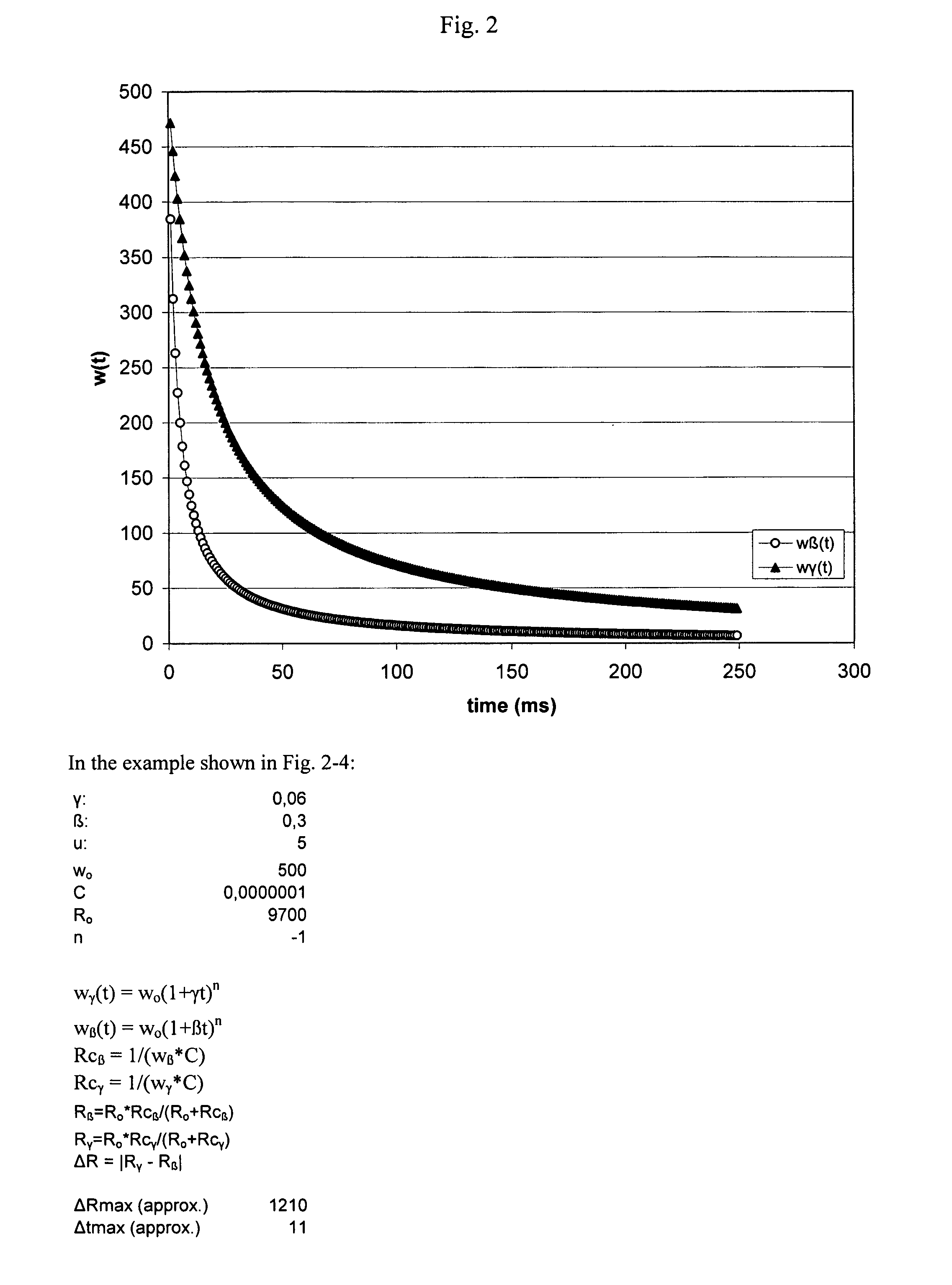
[0088]As shown in the examples, the measurement of the distance x is especially reliable, when an optimized ratio between the frequency rates β and γ is selected. Thus, in one preferred embodiment of the apparatus of the invention, the sweep rates β and γ are selected such that the ratio u=β / γ is a value between 4 and 8 and more preferably between 5 and 7. In a most preferred embodiment the ratio u is selected such that u=5.83.

Problems solved by technology

It is, however, difficult even for a skilled dentist to efficiently perform such a series of operations, which are time-consuming and may cause patients to suffer severe pain.
The aforementioned prior art systems, however suffer from an insufficient signal sensitivity especially when the probe is in close proximity of the tooth apex.

Method used


Image

  • Apparatus and methods for determining the location of the apex of a dental root canal
  • Apparatus and methods for determining the location of the apex of a dental root canal
  • Apparatus and methods for determining the location of the apex of a dental root canal

Examples


example 1

[0111]The following example can be carried out using an apparatus as described e.g. in EP0392518 B1 with the modification that the apparatus of the invention has to be modified to be capable of carrying out a frequency sweep as described herein above and that the apparatus comprises a computing unit as described herein. Regarding the following examples it is to be understood that the following steps and parameters are only exemplary and not limiting.

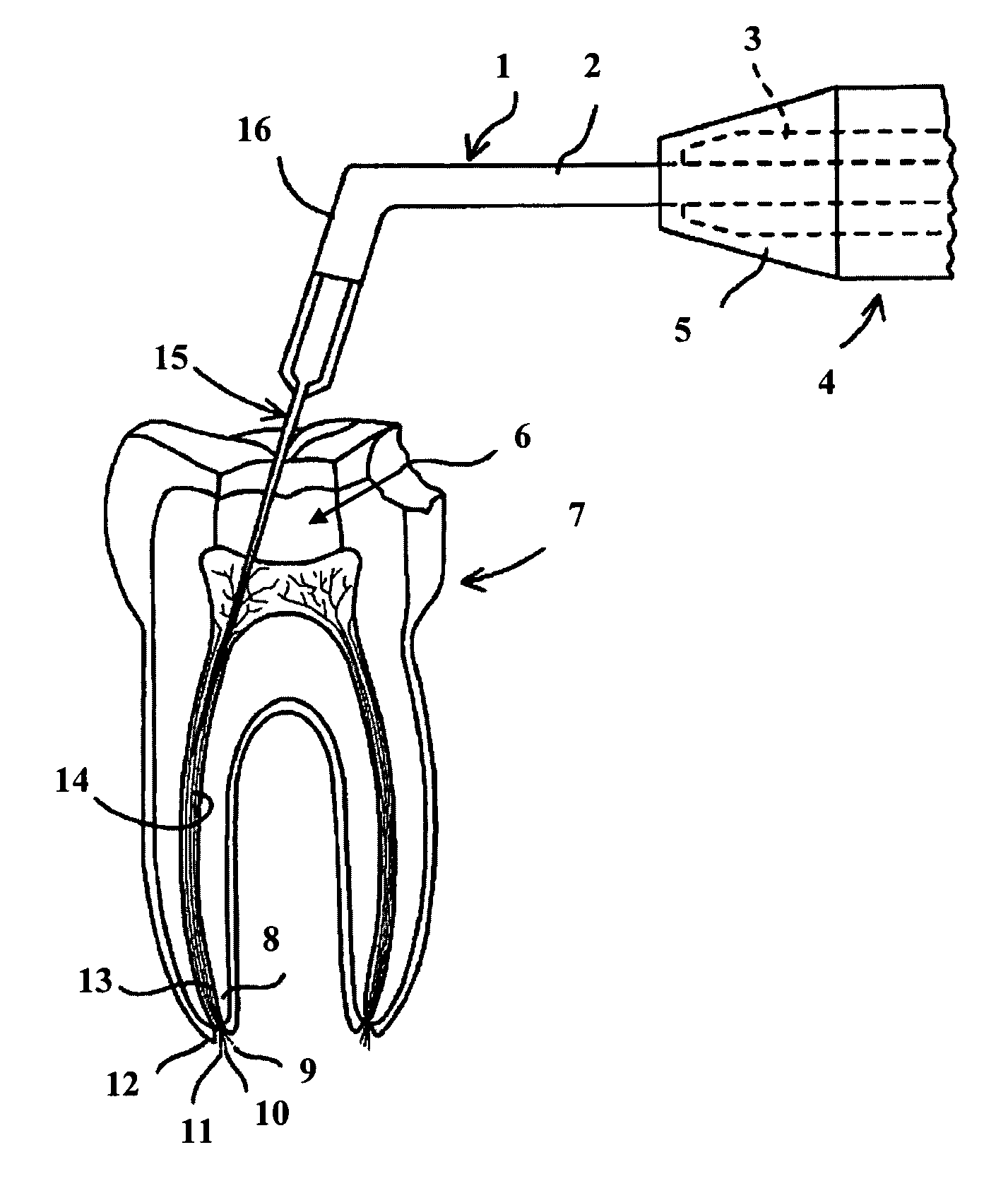
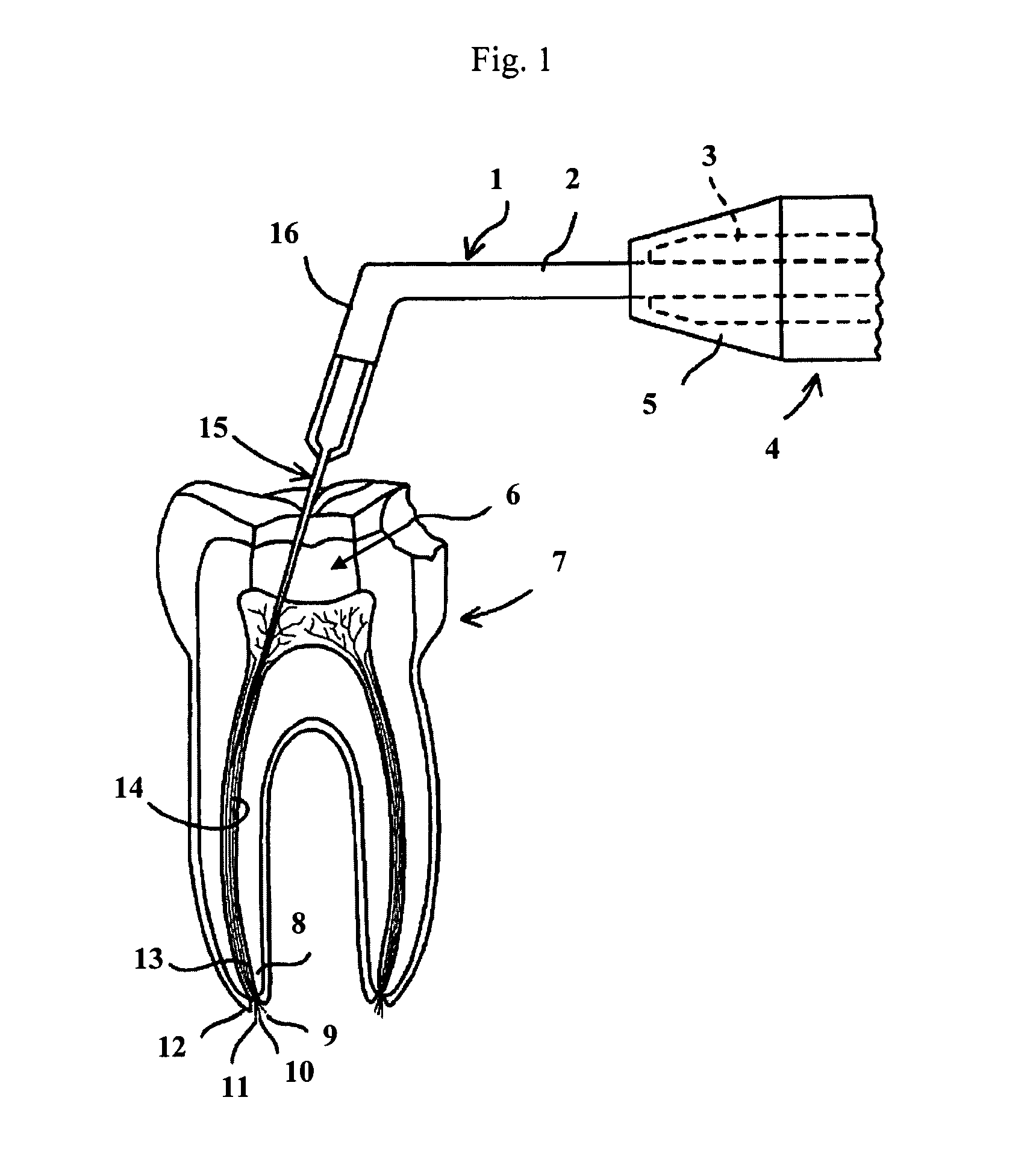
[0112]In a first step, a first electrode which in this example is a needle electrode (15) is inserted into the tooth canal (14). Next the frequency rate γ for the fast first frequency sweep is selected such that the first frequency sweep will be completed preferably within less than 0.6 seconds (see also example 2 below of how to optimize the ratio for the frequency rates β and γ). One exemplary value for γ is shown in FIG. 2. Also shown in FIG. 2 are the parameters and equations that were used for determining the frequencies shown in FI...

example 2

Determining the Optimal Frequency Sweep-Rates β and γ.

[0129]For selecting the optimal frequency sweep rates γ and β two aspects are to be considered so that the impedance measurements can be carried out with optimal accuracy: On one hand the location of the apex should be carried out as fast as possible to allow a nearly real-time display of the electrode position with respect to the tooth apex. Thus, γ should be selected such that the first frequency sweep is completed sufficiently fast, preferably within less than 0 5, more preferably within less than 0.1 seconds. On the other hand, a second slower frequency sweep will be carried out in a preferred embodiment of the apparatus of the invention using a preferably slower frequency sweep rate β. Thus, if the frequency rate γ has been already preset to a value which is known to work well, i.e. to complete the first sweep in time, then it is convenient to determine the frequency sweep rate β from the relationship β=uγ (as u=β / γ). Thus t...


PUM


Abstract

The invention relates to the field of medical methods and equipment and in preferred embodiments to equipment and methods used in dentistry. In particular it relates to an apparatus for determining the location of the apex of a dental root canal wherein the apparatus allows the acquisition of more accurate data in a shorter time span.

Description

FIELD OF THE INVENTION[0001]The invention relates to the field of medical methods and equipment and in preferred embodiments to equipment and methods used in dentistry. In particular it relates to an apparatus for determining the location of the apex of a dental root canal wherein the apparatus allows the acquisition of more accurate data in a shorter time span.BACKGROUND OF THE INVENTION[0002]In root canal therapy, the interior of a root is removed prior to filling the root with replacement material. If the canal is not completely emptied of the root material prior to filling with the replacement material, leftover root material can retard healing and even act as a focus for infection. For this reason, all of the natural interior material in the root is removed before filling.[0003]Both mechanical and chemical means are used to eliminate such germs in the root canal in an effort to prevent further infection. Traditionally this has been done using a mechanical means such as a reamer...

Claims


Application Information

Patent Timeline
Patent Type & Authority Patents(United States)
IPC IPC(8): A61B5/00
CPCA61C19/041A61C19/042
Inventor LAXHUBER, LUDWIG
Owner ENDOSAFE
Learn More